Lab 11
Objective
In Lab 11, we were tasked with performing localization on our robot using a Bayes filter. We implemented only the update step based on a 360-degree scan, as our robots exhibited too much noise for an effective prediction step. This lab aimed to bridge the gap between the simulation environment of Lab 10 and real-world operation.
Simulation
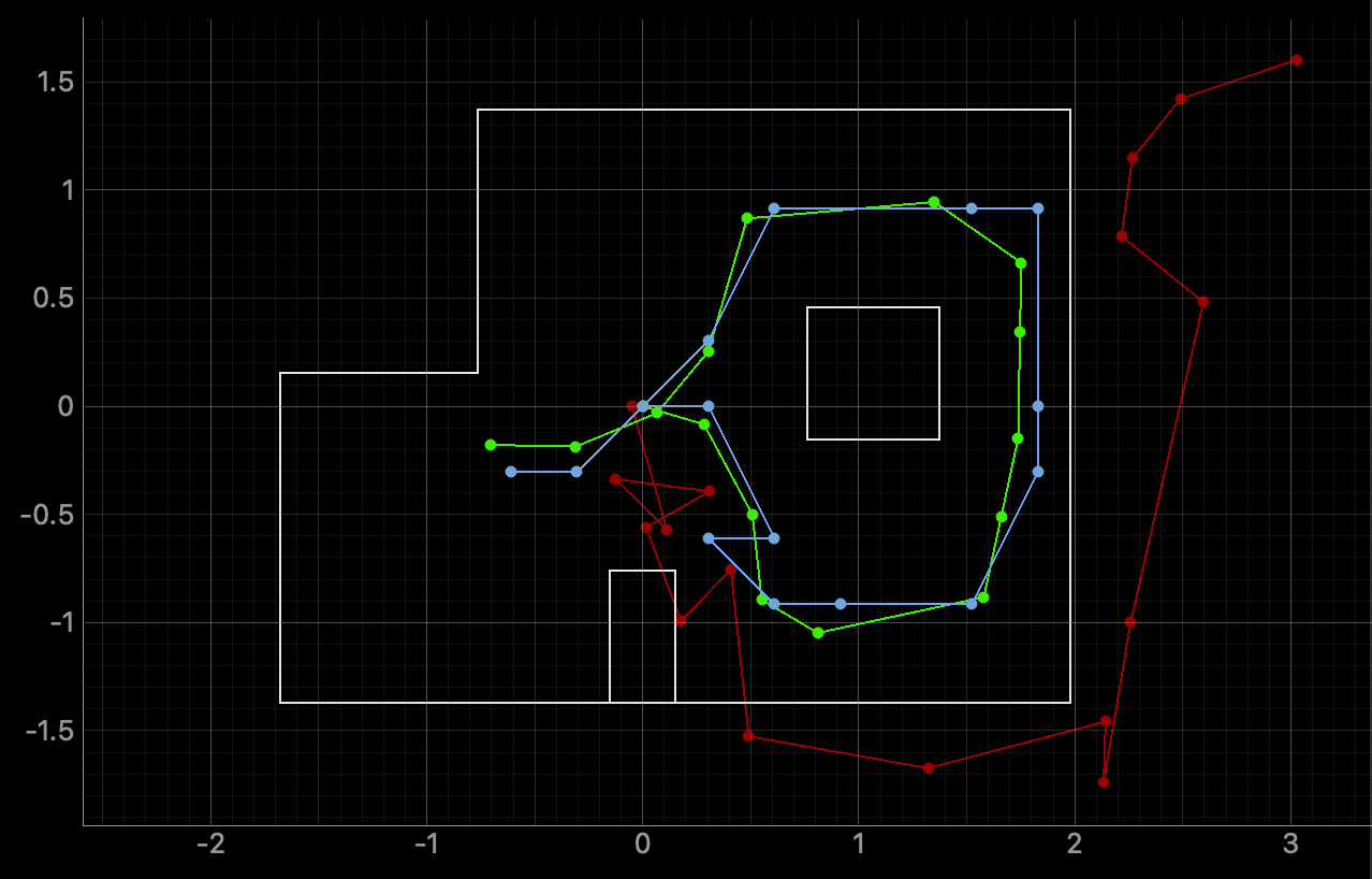
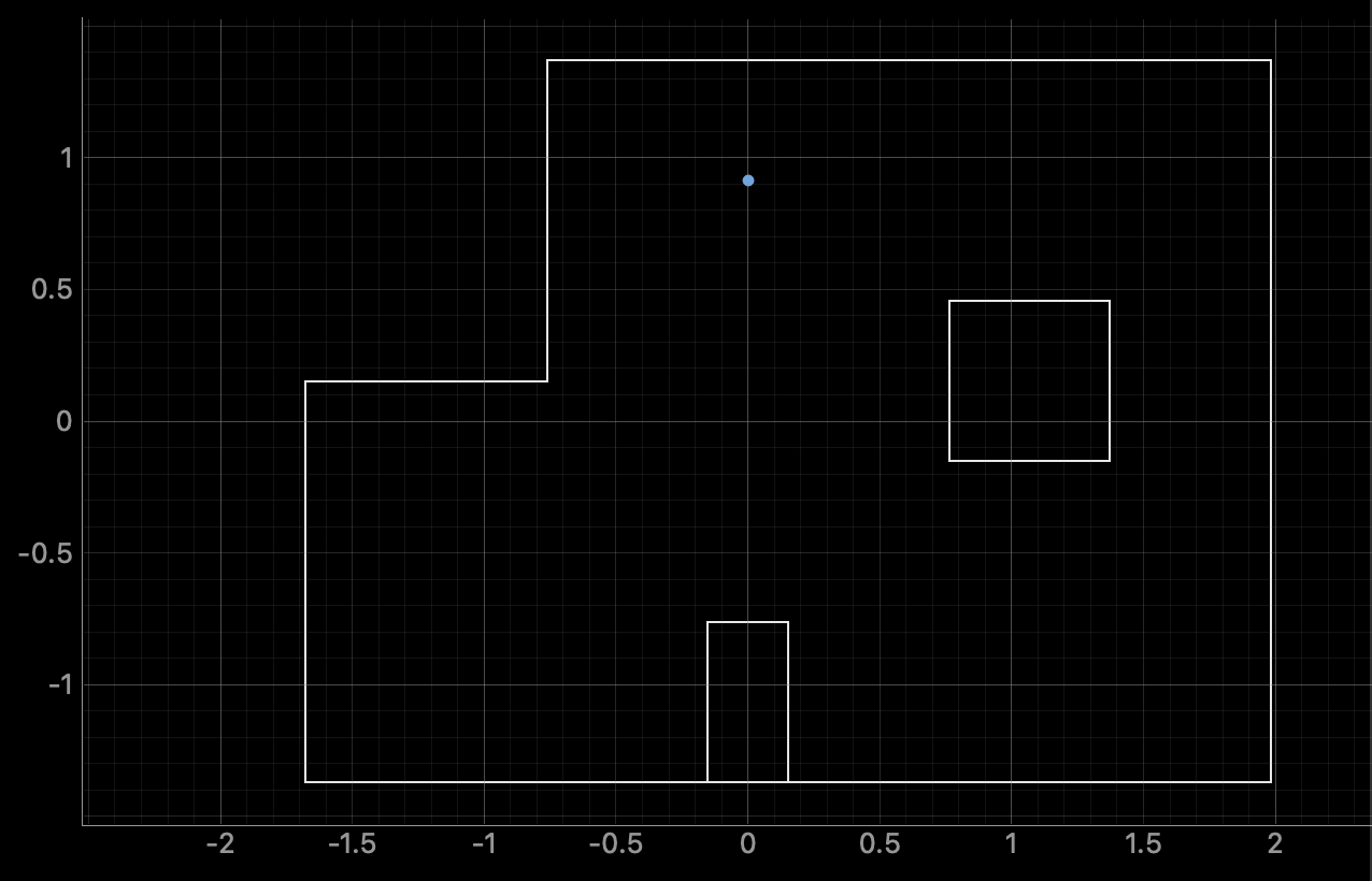
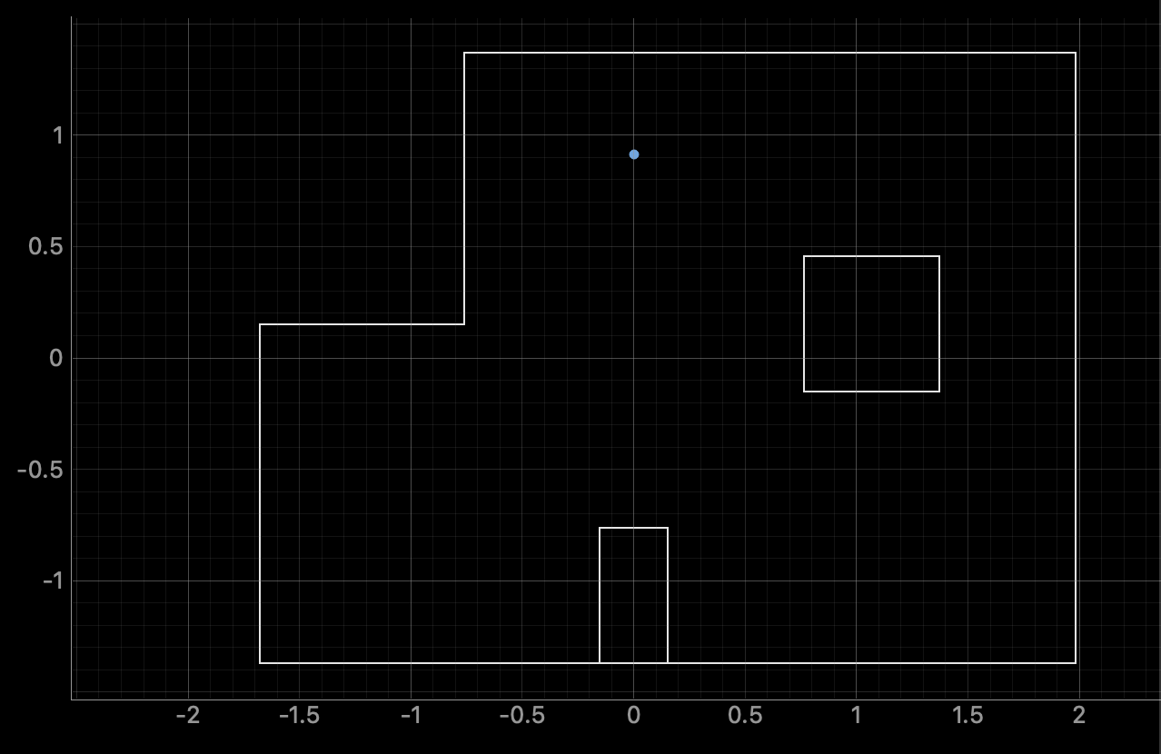
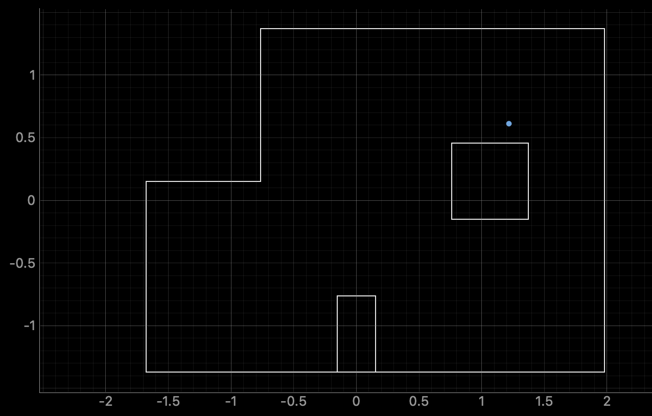
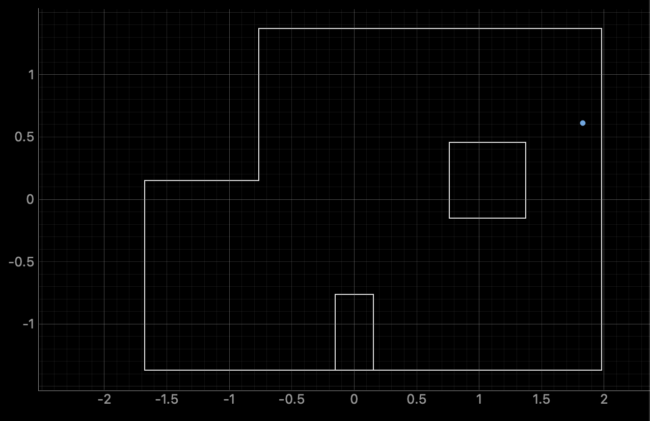
I began by running lab11_sim.ipynb from the provided files. In the resulting plot, red represents the odometry estimate, green shows the ground truth, and blue indicates the belief produced by the Bayes filter.
Implementation
The primary task of Lab 11 was completing the perform_observation_loop function.
def perform_observation_loop(self, rot_vel=120):
        """Perform the observation loop behavior on the real robot, where the robot does
        a 360 degree turn in place while collecting equidistant (in the angular space) sensor
        readings, with the first sensor reading taken at the robot's current heading.
        The number of sensor readings depends on "observations_count"(=18) defined in world.yaml.

        Keyword arguments:
            rot_vel -- (Optional) Angular Velocity for loop (degrees/second)
                        Do not remove this parameter from the function definition, even if you don't use it.
        Returns:
            sensor_ranges   -- A column numpy array of the range values (meters)
            sensor_bearings -- A column numpy array of the bearings at which the sensor readings were taken (degrees)
                               The bearing values are not used in the Localization module, so you may return a empty numpy array
        """
        ble.send_command(CMD.PID, "0.01|0.0000008|0.0007|150|200")
        while (len(distance_data) < 180):
            asyncio.run(asyncio.sleep(3))
        angle_data1 = np.array(angle_data, dtype=float)
        distance_data1 = np.array(distance_data, dtype=float)
        #Convert from mm to m
        distance_data1 /= 1000.0

        angle_array1 = angle_data1.reshape(18, 10).mean(axis=1)
        distance_data1 = distance_data1.reshape(18, 10).mean(axis=1)

        print(angle_array1)

        # normalize to [0, 360)
        angles_360 = (angle_array1 + 360) % 360
        print(angles_360)

        # reflect across the 180° axis
        angles_reflect = (360 - angles_360) % 360

        sensor_ranges = np.array(distance_data1)[np.newaxis].T
        sensor_bearings = np.array(angles_reflect)[np.newaxis].T

        print(sensor_ranges)
        print(sensor_bearings)

        return sensor_ranges, sensor_bearings
In this function, I used a Bluetooth PID command, which is a modified version of the command developed in Lab 9. The modification allows the robot to collect 18 data points at 20-degree increments, instead of the 15 points at 24-degree increments used previously.
void loop() {
   BLEDevice central = BLE.central();
   if (central) {
       while (central.connected()) {
           write_data();
           read_data();


           if (PID_flag) {
               unsigned long stabilizationStart = millis();
               while (millis() - stabilizationStart < 2000) {
                   icm_20948_DMP_data_t dummyData;
                   myICM.readDMPdataFromFIFO(&dummyData);
                   delay(5);
               }


               start_time_1 = millis();
               bool yaw_offset_set = false;
               double yaw_offset_deg = 0.0;
               sensor2.startRanging();


               static int distance_count = 0;
               static int last_stage = -1;


               while (millis() - start_time_1 < 54000 && PID_flag && central.connected()) {
                   icm_20948_DMP_data_t dmpData;
                   myICM.readDMPdataFromFIFO(&dmpData);
                   if ((myICM.status == ICM_20948_Stat_Ok) ||
                       (myICM.status == ICM_20948_Stat_FIFOMoreDataAvail)) {
                       if ((dmpData.header & DMP_header_bitmap_Quat9) > 0) {
                           double q1 = ((double)dmpData.Quat9.Data.Q1) / 1073741824.0;
                           double q2 = ((double)dmpData.Quat9.Data.Q2) / 1073741824.0;
                           double q3 = ((double)dmpData.Quat9.Data.Q3) / 1073741824.0;
                           double q0 = sqrt(1.0 - ((q1 * q1) + (q2 * q2) + (q3 * q3)));
                           double yaw = atan2(2.0 * (q0 * -q3 + q1 * q2), 1.0 - 2.0 * ((q1 * q1) + (q3 * q3)));
                           double current_yaw_deg = yaw * 180.0 / M_PI;
                           if (current_yaw_deg < 0) {
                               current_yaw_deg += 360;
                           }


                           if (!yaw_offset_set) {
                               yaw_offset_deg = current_yaw_deg;
                               yaw_offset_set = true;
                           }


                           double yaw_relative = current_yaw_deg - yaw_offset_deg;
                           while (yaw_relative > 180) yaw_relative -= 360;
                           while (yaw_relative < -180) yaw_relative += 360;


                           unsigned long pid_elapsed = millis() - start_time_1;
                           int stage = pid_elapsed / 3000;
                           if (stage > 17) stage = 17;


                           double setpoints[18] = {0.0, 340.0, 320.0, 300.0, 280.0, 260.0, 240.0, 220.0, 200.0, 180.0, 160.0, 140.0, 120.0, 100.0, 80.0, 60.0, 40.0, 20.0};
                           double setpoint = setpoints[stage];
                           if (setpoint > 180) setpoint -= 360;


                           double error = yaw_relative - setpoint;
                           while (error > 180) error -= 360;
                           while (error < -180) error += 360;


                           unsigned long now = millis();
                           double dt = (now - last_time) / 1000.0;
                           if (dt <= 0) dt = 0.001;
                           if (dt > 1) dt = 0.0001;
                           last_time = now;


                           if (dt == 0.0001) derivative = 0;
                           else derivative = (error - last_error) / dt;
                           last_error = error;


                           double pid_output = Kp * error + Ki * integral + Kd * derivative;
                           double pid_pwm = PWM_MIN + pid_output;


                           if (!((error > 0 && pid_output > 0 && pid_output + PWM_MIN == PWM_MAX) ||
                                 (error < 0 && pid_output < 0 && pid_output - PWM_MIN == -PWM_MAX))) {
                               integral += error * dt;
                           }


                           pid_pwm = constrain(pid_pwm, PWM_MIN, PWM_MAX);
                           int pwmValue = (int) pid_pwm;


                           if (fabs(error) < 2.0) {
                               analogWrite(AIN1, 0);
                               analogWrite(AIN2, 0);
                               analogWrite(BIN1, 0);
                               analogWrite(BIN2, 0);


                               // Reset distance count for new stage
                               if (stage != last_stage) {
                                   distance_count = 0;
                                   last_stage = stage;
                               }


                               if (distance_count < 10 && sensor2.checkForDataReady()) {
                                   last_distance = sensor2.getDistance();
                                   distances[index_1] = last_distance;
                                   yaws[index_1] = yaw_relative;
                                   sensor2.clearInterrupt();
                                   Serial.print("Distance ");
                                   Serial.print(distance_count + 1);
                                   Serial.print(": ");
                                   Serial.print(last_distance);
                                   Serial.println(" mm");
                                   distance_count++;
                                   index_1++;
                               }
                           } else {
                               if (pid_output >= 0) {
                                   analogWrite(AIN1, 0);
                                   analogWrite(BIN1, 0);
                                   analogWrite(AIN2, (int)(1.25 * pwmValue));
                                   analogWrite(BIN2, (int)(1.35 * pwmValue));
                                   pwm_vals[index_1] = pwmValue;
                               } else {
                                   analogWrite(AIN2, 0);
                                   analogWrite(BIN2, 0);
                                   analogWrite(AIN1, (int)(1.2 * pwmValue));
                                   analogWrite(BIN1, (int)(1.25 * pwmValue));
                                   pwm_vals[index_1] = -pwmValue;
                               }
                           }
                       }
                   }
               }


               sensor2.stopRanging();

               ###Transmit data###

               PID_flag = false;
               index_1 = 0;
           }
       }
       Serial.println("Disconnected");
   }
}
Additionally, the updated PID command iterates through setpoints in reverse order to achieve counterclockwise rotation, contrasting with the clockwise rotation demonstrated in Lab 9. However, because the robot interprets positive rotation as clockwise while the Bayes filter assumes positive rotation is counterclockwise, further angle processing was necessary. Within perform_observation_loop, I normalized the angles from the range [−180, 180] to [0, 360] and reflected them across 180 degrees. This ensured the measured distances were correctly mapped to the Bayes filter's angle convention.
Results
(-3, -2)
(0, 3)

(5, 3)
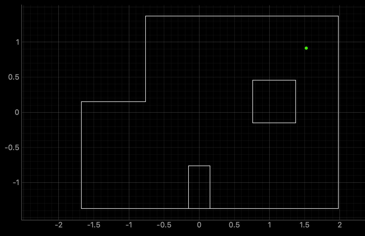
(5, -3)
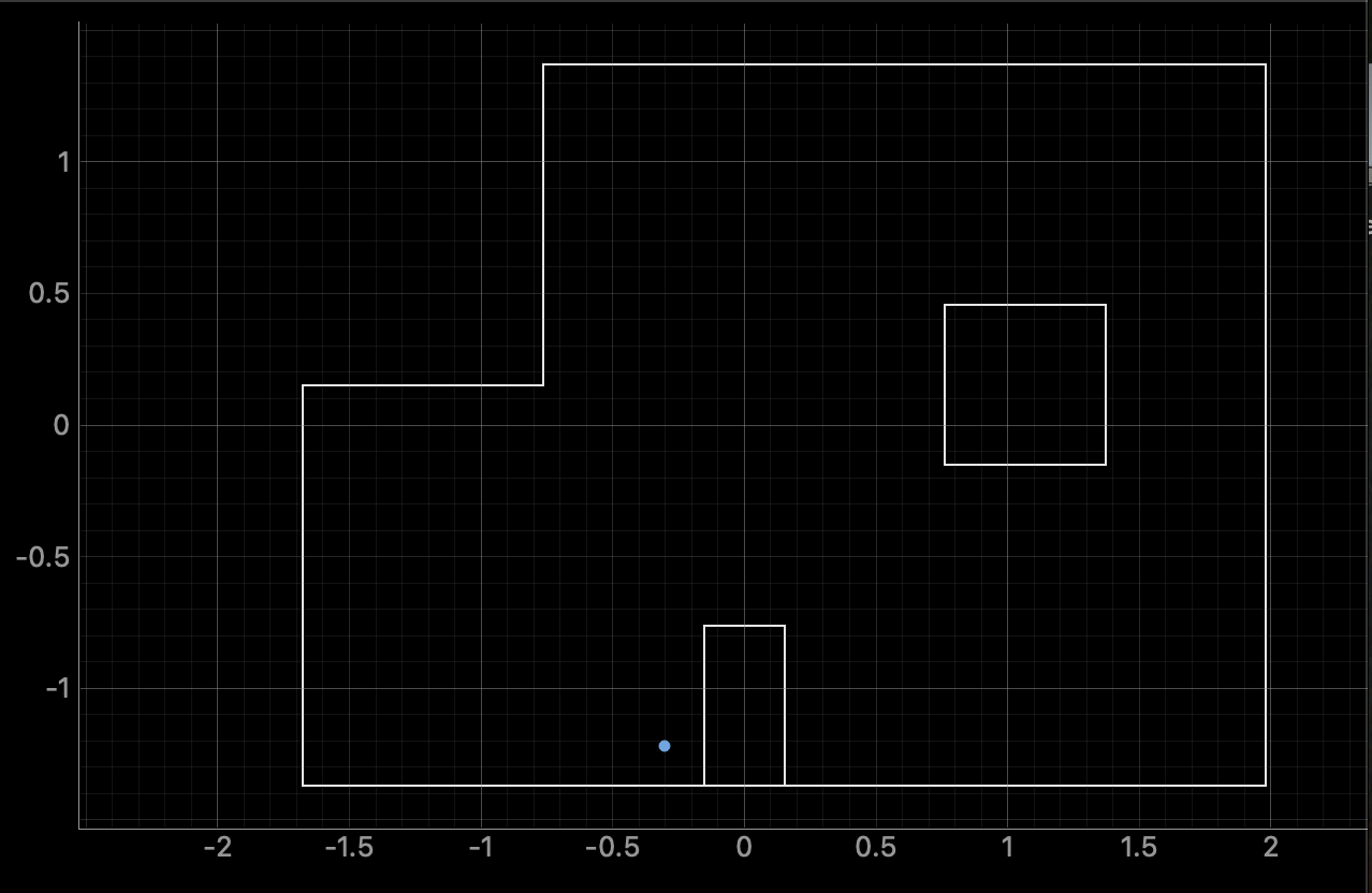
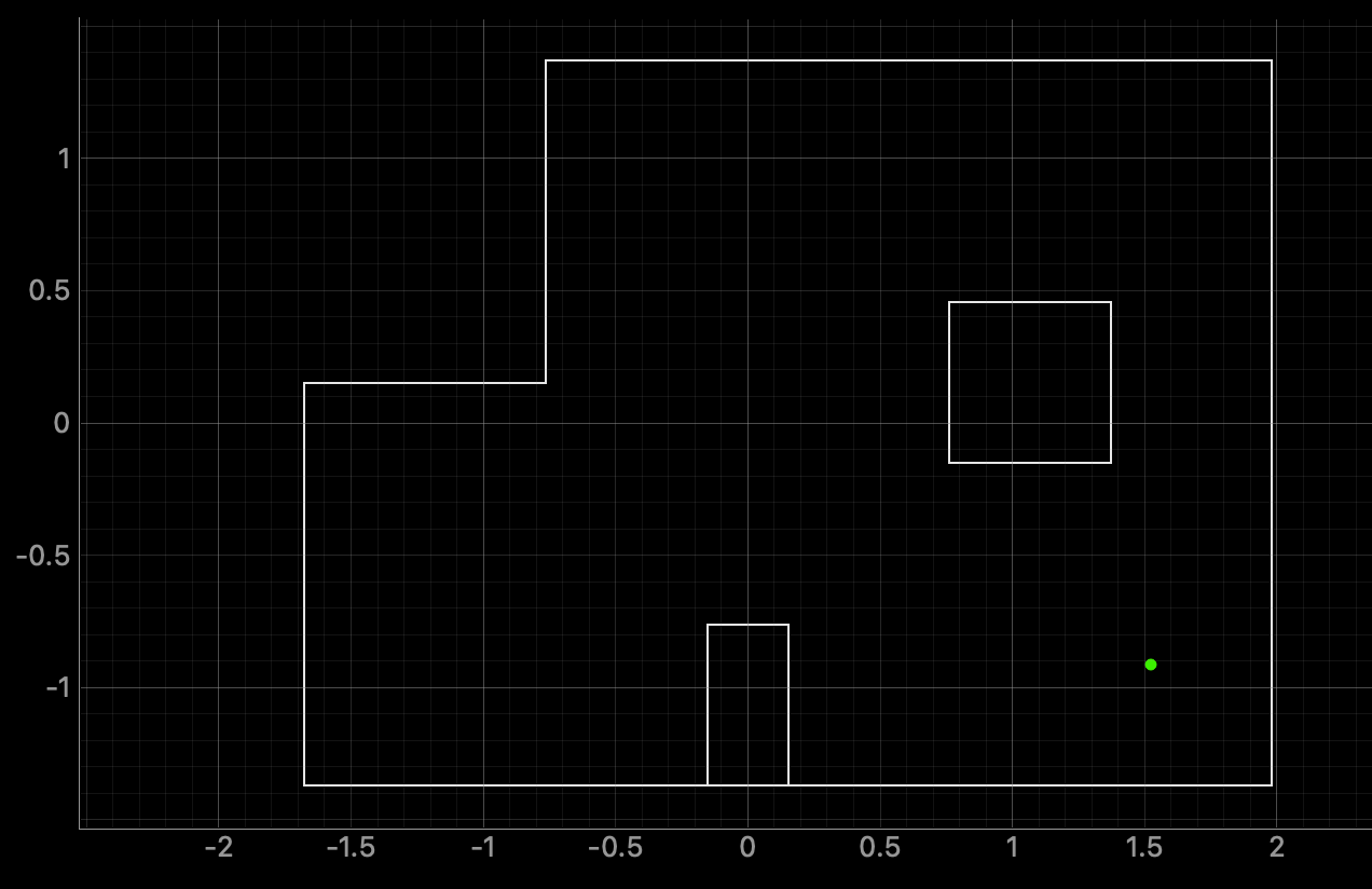
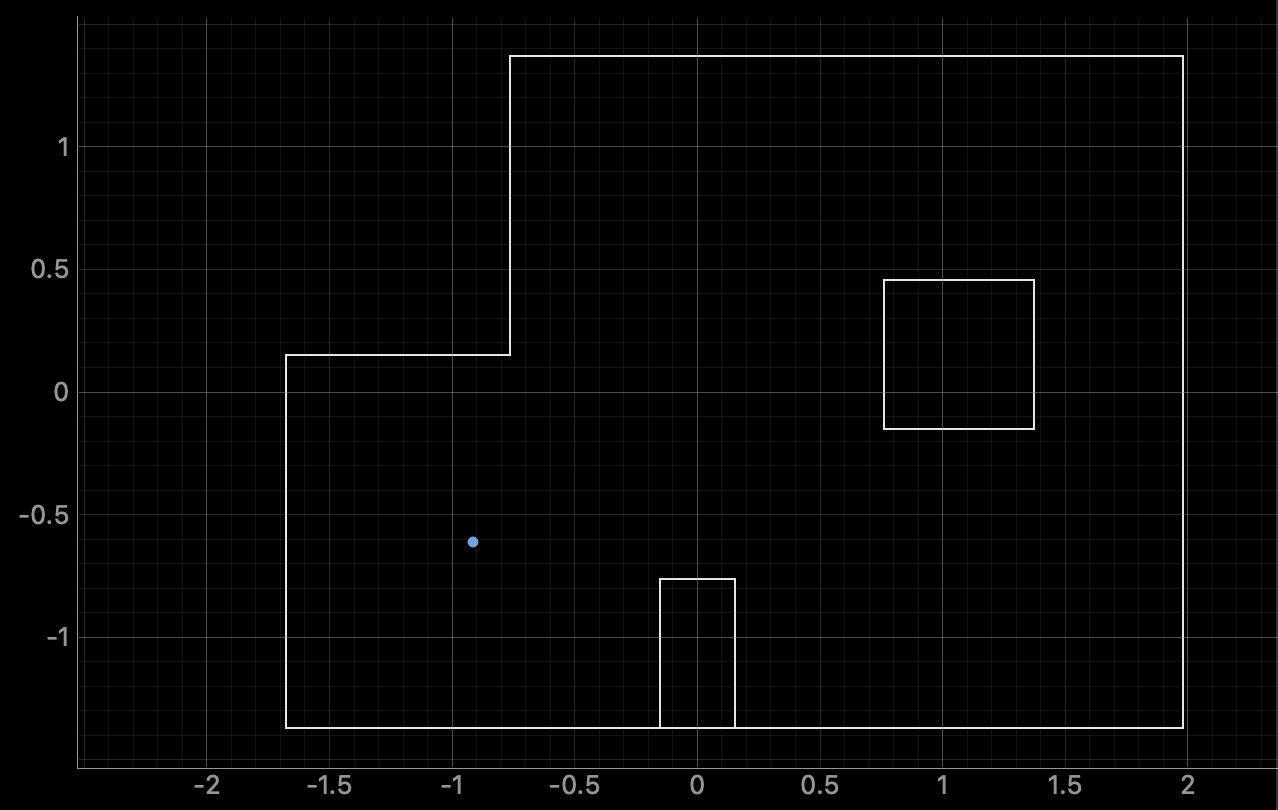
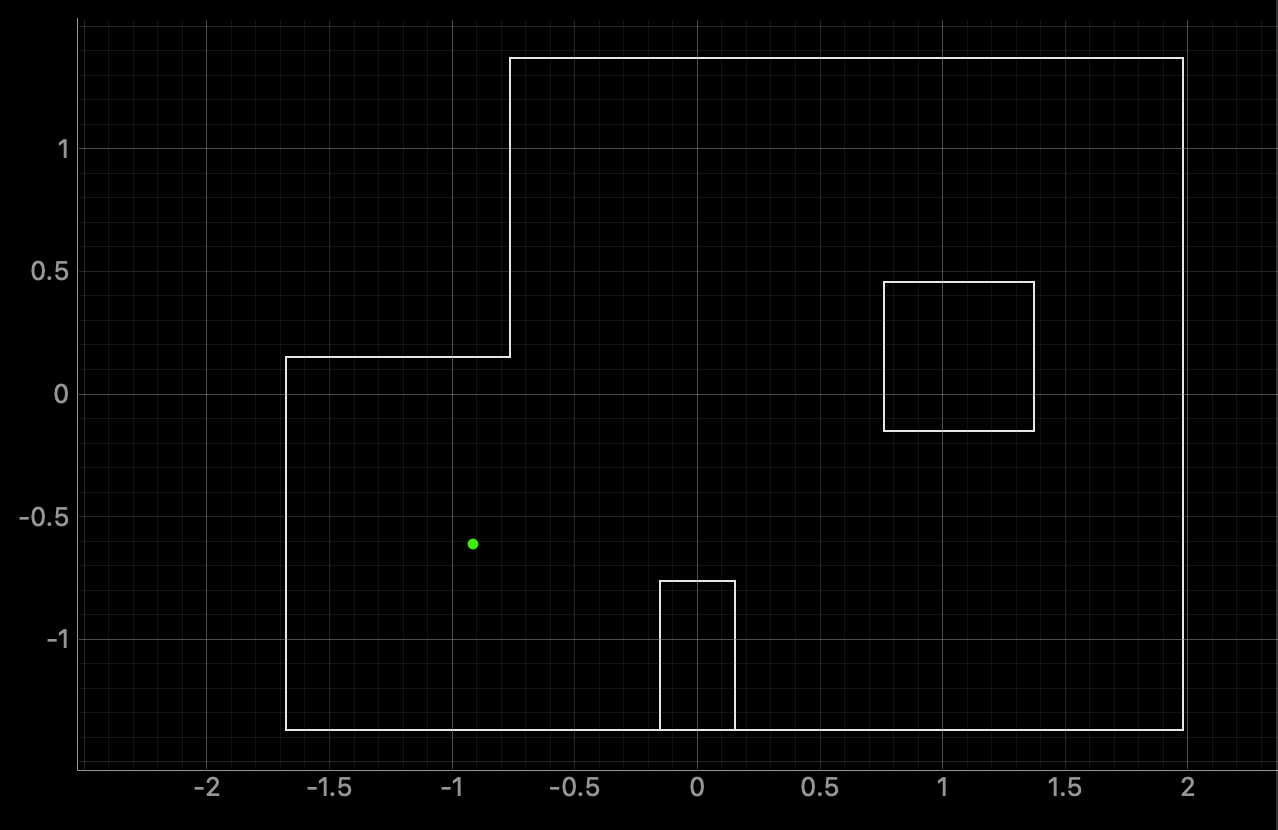
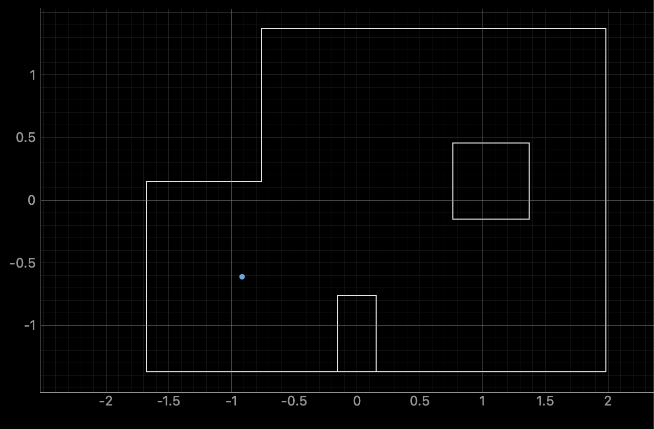
For 3 out of the 4 test locations, I achieved fairly accurate localization results. However, at the point (5, -3), my robot struggled to localize correctly. This issue stems from the limitations of my Time of Flight (ToF) sensors, which are only effective up to approximately 2 meters. At (5, -3), the far wall, a key distinguishing feature of that location, is beyond this sensing range. As a result, the ToF sensors failed to detect it, making it difficult for the Bayes filter to differentiate this location from others. I attempted several adjustments, including increasing the ToF sensor’s ranging time, modifying the intermediate timing period, and even swapping sensors. Unfortunately, none of these changes extended the range enough to detect the far wall. Despite this, the returned polar plot was consistent with what was observed in Lab 9, and the global frame transformation generally matched the environment.
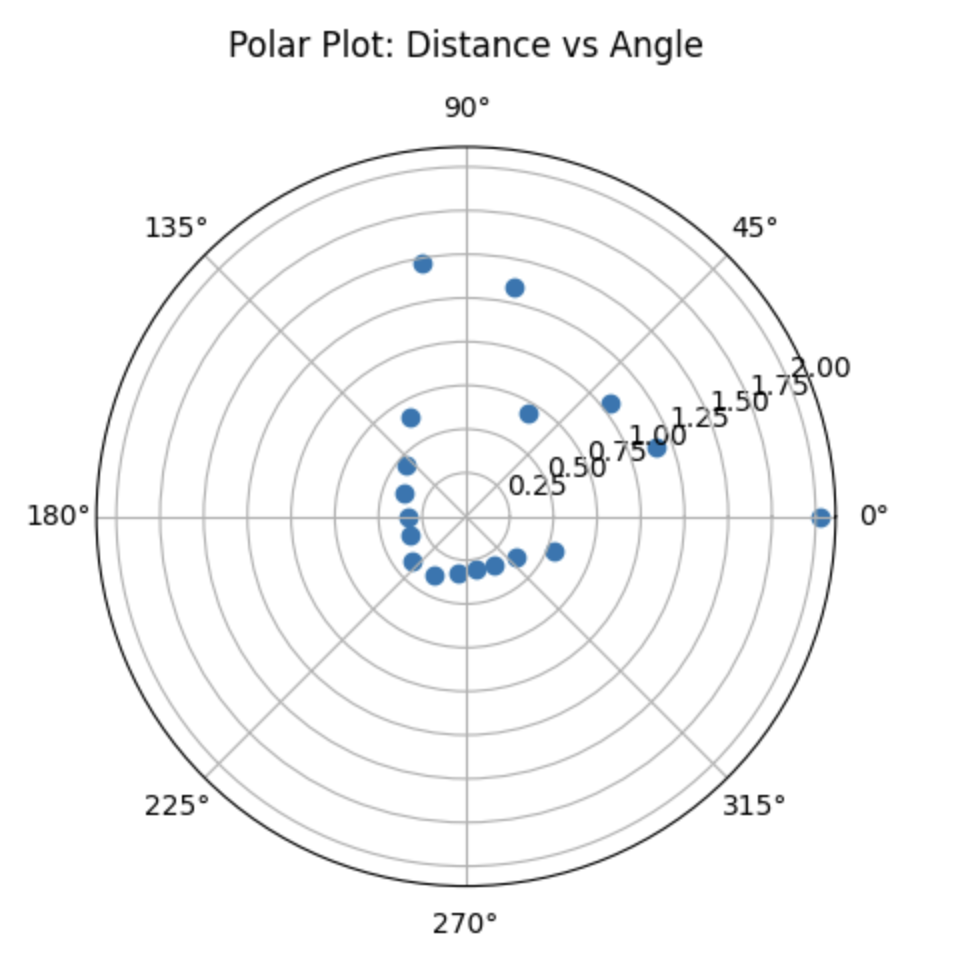
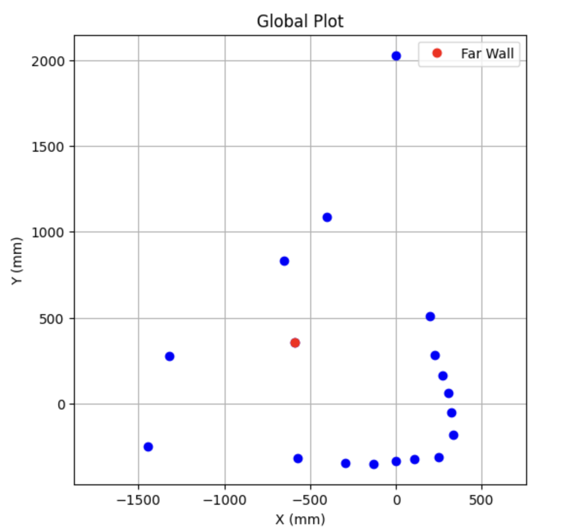
This confirmed that my implementation was working correctly from a software and coordinate transformation perspective. To illustrate the impact of missing the far wall, I overlaid the environmental boundaries onto the global frame.
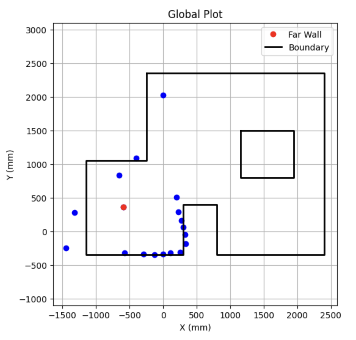
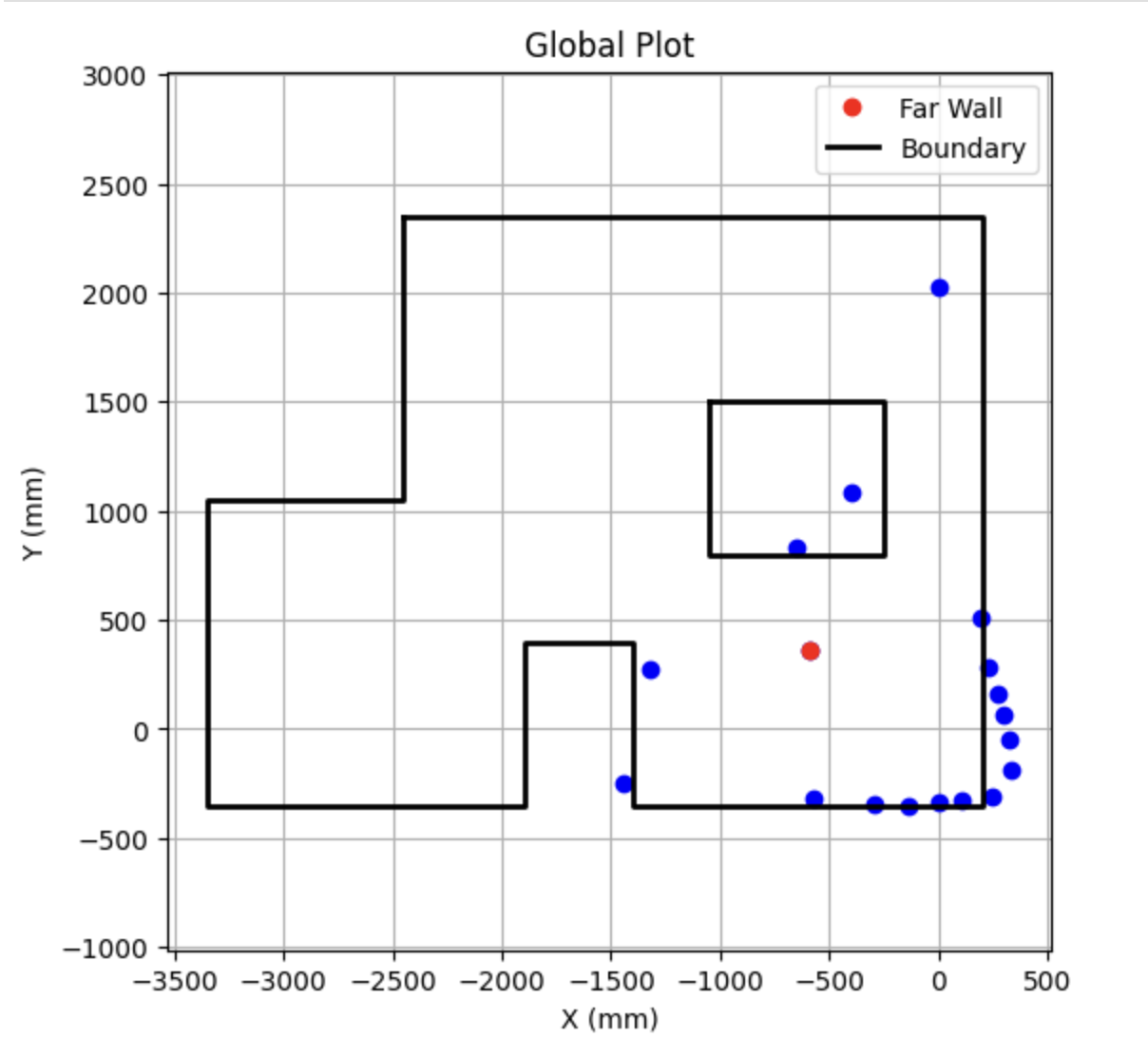
This highlights the source of confusion: the point estimated by localization aligns more closely with the global scan data collected during the 360° sweep than with the actual position at (5, -3). The inability to observe the far wall thus led to incorrect, but internally consistent, localization. Generally speaking, localization performance is better in locations that generate distinct and unique scans additionally, when walls are in close proximity it is able to capture all the key identifying features of a location.
Refrences
In Lab 11, I referenced Daria Kot's and Annabel Lian's webpages. I also used ChatGPT to assist with plot generation and text editing.