Lab 12
Objective
In Lab 12, our task was to program our car to navigate the environment and reach a series of waypoints. This was an open-ended assignment that encouraged us to build upon the functionality developed throughout the first 11 labs. For my approach, I chose to implement feedback control. Due to the limited range of my time-of-flight (ToF) sensors, I was not confident in the car’s ability to perform reliable localization or path planning. As observed in Labs 9 and 11, both of my ToF sensors struggled to produce consistent distance measurements beyond approximately 2 meters. Given this constraint, my car’s ability to navigate between waypoints depended on the presence of nearby walls, which were necessary to provide the distance feedback required by my linear PID controller.
Implementation
To tackle this lab, I modified the code from Labs 5 and 6 to create dedicated functions for linear and angular PID control. As I noted in Lab 6, when I first begin collecting data from the DMP (Digital Motion Processor), the initial readings are extremely noisy for the first few seconds. Once the readings stabilize, a small steady-state error remains, which I use to zero the controller. Because I want this to be performed only once when I start the DMP, This is performed in my command prior to any calls to angular or linear PID functions.
case PID:
            float Kp, Ki, Kd, PWM_MIN, PWM_MAX, Kp1, Ki1, Kd1, PWM_MIN1, PWM_MAX1, PID_DISTANCE, SCALE;

            success = robot_cmd.get_next_value(Kp);
            if (!success) return;

            success = robot_cmd.get_next_value(Ki);
            if (!success) return;

            success = robot_cmd.get_next_value(Kd);
            if (!success) return;

            success = robot_cmd.get_next_value(PWM_MIN);
            if (!success) return;

            success = robot_cmd.get_next_value(PWM_MAX);
            if (!success) return;

            success = robot_cmd.get_next_value(Kp1);
            if (!success) return;

            success = robot_cmd.get_next_value(Ki1);
            if (!success) return;

            success = robot_cmd.get_next_value(Kd1);
            if (!success) return;

            success = robot_cmd.get_next_value(PWM_MIN1);
            if (!success) return;

            success = robot_cmd.get_next_value(PWM_MAX1);
            if (!success) return;

            success = robot_cmd.get_next_value(PID_DISTANCE);
            if (!success) return;

            success = robot_cmd.get_next_value(SCALE);
            if (!success) return;

            Serial.println(Kp);
            Serial.println(Ki);
            Serial.println(Kd);
            Serial.println(PWM_MIN);
            Serial.println(PWM_MAX);

            stabilizationStart = millis();
            while (millis() - stabilizationStart < 3000) {
                icm_20948_DMP_data_t dummyData;
                myICM.readDMPdataFromFIFO(&dummyData);
                delay(5);
            }

            rotateToAngle(0.0, Kp1, Ki1, Kd1, PWM_MIN1, PWM_MAX1);
            rotateToAngle(270.0, Kp1, Ki1, Kd1, PWM_MIN1, PWM_MAX1);
            performDistancePID(705, Kp, Ki, Kd, PWM_MIN, PWM_MAX, SCALE);
            rotateToAngle(0.0, Kp1, Ki1, Kd1, PWM_MIN1, PWM_MAX1);
            performDistancePID(400, Kp, Ki, Kd, PWM_MIN, PWM_MAX, SCALE);
            rotateToAngle(270.0, Kp1, Ki1, Kd1, PWM_MIN1, PWM_MAX1);
            performDistancePID(400, Kp, Ki, Kd, PWM_MIN, PWM_MAX, SCALE);
            rotateToAngle(180.0, Kp1, Ki1, Kd1, PWM_MIN1, PWM_MAX1);
            performDistancePID(400, Kp, Ki, Kd, PWM_MIN, PWM_MAX, SCALE);
            rotateToAngle(270.0, Kp1, Ki1, Kd1, PWM_MIN1, PWM_MAX1);
            performDistancePID(350, Kp, Ki, Kd, PWM_MIN, PWM_MAX, SCALE);
            rotateToAngle(0.0, Kp1, Ki1, Kd1, PWM_MIN1, PWM_MAX1);
            performDistancePID(400, Kp, Ki, Kd, PWM_MIN, PWM_MAX, SCALE);
            rotateToAngle(90.0, Kp1, Ki1, Kd1, PWM_MIN1, PWM_MAX1);
            performDistancePID(705, Kp, Ki, Kd, PWM_MIN, PWM_MAX, SCALE);
            rotateToAngle(180.0, Kp1, Ki1, Kd1, PWM_MIN1, PWM_MAX1);
            performDistancePID(705, Kp, Ki, Kd, PWM_MIN, PWM_MAX, SCALE);
            break;
For angular PID, the car rotates until it settles within ±1 degree of the desired setpoint. Initially, at each new call to the angular PID function, I would restart DMP data collection and re-zero it. This approach introduced inconsistency. Although the angular PID controller itself performed well in isolation, the repeated re-zeroing caused small angular offsets to accumulate over time. As a result, the car's orientation became increasingly unreliable when navigating between later waypoints.
To resolve this, I modified the angular PID function so that it zeroes the DMP only once at the beginning of the run. This change ensures that the car's angular reference frame remains consistent throughout the entire navigation task. Although there may be a small error after each angular PID call it doesn't meaningfully affect the car’s performance or cause further compounding error. This led to much more reliable and predictable orientation behavior as the car moved through the environment. You can observe that the command begins with two consecutive calls to the rotateToAngle function. This is because the first call does not perform any PID control, it just zeros the angle.
void rotateToAngle(float targetDeg, float Kp, float Ki, float Kd,float PWM_MIN, float PWM_MAX){
    static bool  yawOffsetSet  = false;
    static double yawOffsetDeg = 0.0;

    icm_20948_DMP_data_t dmpData;
    if (!yawOffsetSet) {
        do {
            myICM.readDMPdataFromFIFO(&dmpData);
        } while (!((myICM.status == ICM_20948_Stat_Ok ||
                    myICM.status == ICM_20948_Stat_FIFOMoreDataAvail) &&
                   (dmpData.header & DMP_header_bitmap_Quat9)));

        double q1 = double(dmpData.Quat9.Data.Q1) / 1073741824.0;
        double q2 = double(dmpData.Quat9.Data.Q2) / 1073741824.0;
        double q3 = double(dmpData.Quat9.Data.Q3) / 1073741824.0;
        double q0 = sqrt(1.0 - (q1*q1 + q2*q2 + q3*q3));
        double yaw = atan2(2*(q0*q3 + q1*q2), 1 - 2*(q2*q2 + q3*q3)) * 180.0/M_PI;
        if (yaw >  180) yaw -= 360;
        if (yaw < -180) yaw += 360;

        yawOffsetDeg = yaw;
        yawOffsetSet = true;
        return;
    }

    unsigned long last_time = millis();
    double integral    = 0;
    double last_error  = 0;
    double error       = 1e6;

    while (fabs(error) >= 1.0) {
        myICM.readDMPdataFromFIFO(&dmpData);
        if ((myICM.status == ICM_20948_Stat_Ok) ||
            (myICM.status == ICM_20948_Stat_FIFOMoreDataAvail)) {

            if (dmpData.header & DMP_header_bitmap_Quat9) {
                double q1 = double(dmpData.Quat9.Data.Q1) / 1073741824.0;
                double q2 = double(dmpData.Quat9.Data.Q2) / 1073741824.0;
                double q3 = double(dmpData.Quat9.Data.Q3) / 1073741824.0;
                double q0 = sqrt(1.0 - (q1*q1 + q2*q2 + q3*q3));
                double yaw = atan2(2*(q0*q3 + q1*q2), 1 - 2*(q2*q2 + q3*q3)) * 180.0/M_PI;
                if (yaw >  180) yaw -= 360;
                if (yaw < -180) yaw += 360;

                double yawRel = yaw - yawOffsetDeg;
                while (yawRel >  180) yawRel -= 360;
                while (yawRel < -180) yawRel += 360;

                error = targetDeg - yawRel;
                while (error >  180) error -= 360;
                while (error < -180) error += 360;
                Serial.print("yawRel: ");
                Serial.println(yawRel);
                Serial.print("targetDeg: ");
                Serial.println(targetDeg);
                Serial.print("error: ");
                Serial.println(error);

                unsigned long now = millis();
                double dt = (now - last_time) / 1000.0;
                last_time = now;
                if (dt <= 0) dt = 0.001;

                integral   += error * dt;
                double derivative = (error - last_error) / dt;
                last_error = error;

                double pid_output = Kp * error + Ki * integral + Kd * derivative;
                double pid_pwm = constrain(PWM_MIN + pid_output, PWM_MIN, PWM_MAX);
                int pwmValue = int(pid_pwm);

                if (pid_output >= 0) {
                    analogWrite(AIN1, 0);
                    analogWrite(BIN1, 0);
                    analogWrite(AIN2, int(1.25 * pwmValue));
                    analogWrite(BIN2, int(1.35 * pwmValue));
                } else {
                    analogWrite(AIN2, 0);
                    analogWrite(BIN2, 0);
                    analogWrite(AIN1, int(1.2  * pwmValue));
                    analogWrite(BIN1, int(1.25 * pwmValue));
                }
            }
        }
    }

    analogWrite(AIN1, 255);
    analogWrite(AIN2, 255);
    analogWrite(BIN1, 255);
    analogWrite(BIN2, 255);
}
As for linear PID, the controller performed well in Lab 5 and required minimal modification. In the current implementation, my linear PID function continues to collect DMP data, even though it does not use it directly. This design choice is intentional, by continuously reading from the DMP during linear motion, I prevent its FIFO buffer from overflowing, which would otherwise make the data unusable when angular PID is needed. With both PID functions working reliably, I developed a higher-level command above that takes in PID parameters and coordinates a sequence of linear and angular PID calls. This structure enables the car to execute a series of controlled movements through the environment and reach its waypoints effectively.
void performDistancePID(float targetDist, float Kp, float Ki, float Kd, float PWM_MIN, float PWM_MAX, float scale){
    unsigned long last_time = millis();
    double       integral  = 0;
    double       last_error = 0;
    int          index     = 0;
    double       error     = 1e6;

    sensor2.startRanging();
    while (fabs(error) >= 20.0) {
        {
            icm_20948_DMP_data_t dummy;
            myICM.readDMPdataFromFIFO(&dummy);
        }
        if (sensor2.checkForDataReady()) {
            float distance = sensor2.getDistance();
            sensor2.clearInterrupt();

            unsigned long now = millis();
            double dt = (now - last_time) / 1000.0;
            if (dt <= 0) dt = 0.001;
            last_time = now;

            error = distance - targetDist;  // STOP_DISTANCE == 340

            integral   += error * dt;
            double derivative = (error - last_error) / dt;
            last_error = error;

            double pid_out = Kp * error + Ki * integral + Kd * derivative;
            double pid_pwm = constrain(PWM_MIN + pid_out, PWM_MIN, PWM_MAX);
            int    pwmValue = (int)pid_pwm;

            if (pid_out >= 0) {
                analogWrite(AIN2, pwmValue);
                analogWrite(BIN1, (int)(scale * pwmValue));
                analogWrite(AIN1, 0);
                analogWrite(BIN2, 0);
            } else {
                analogWrite(AIN1, pwmValue);
                analogWrite(BIN2, (int)(scale * pwmValue));
                analogWrite(AIN2, 0);
                analogWrite(BIN1, 0);
            }

            index++;

            sensor2.startRanging();
        }
    }

    sensor2.stopRanging();

    analogWrite(AIN1, 255);
    analogWrite(AIN2, 255);
    analogWrite(BIN1, 255);
    analogWrite(BIN2, 255);
}
I modified my PID function to handle the navigation, and it was called in Python using the following code.
ble.send_command(CMD.PID, "0.003|0.0000001|0.0007|35|85|0.01|0.00005|0.0007|100|200|400|1.5")
Given that I could reliably depend only on my linear and angular PID controllers, I aimed to develop a navigation strategy that allowed me to hit as many waypoints as possible using just those control modes.
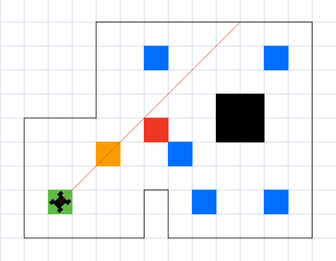
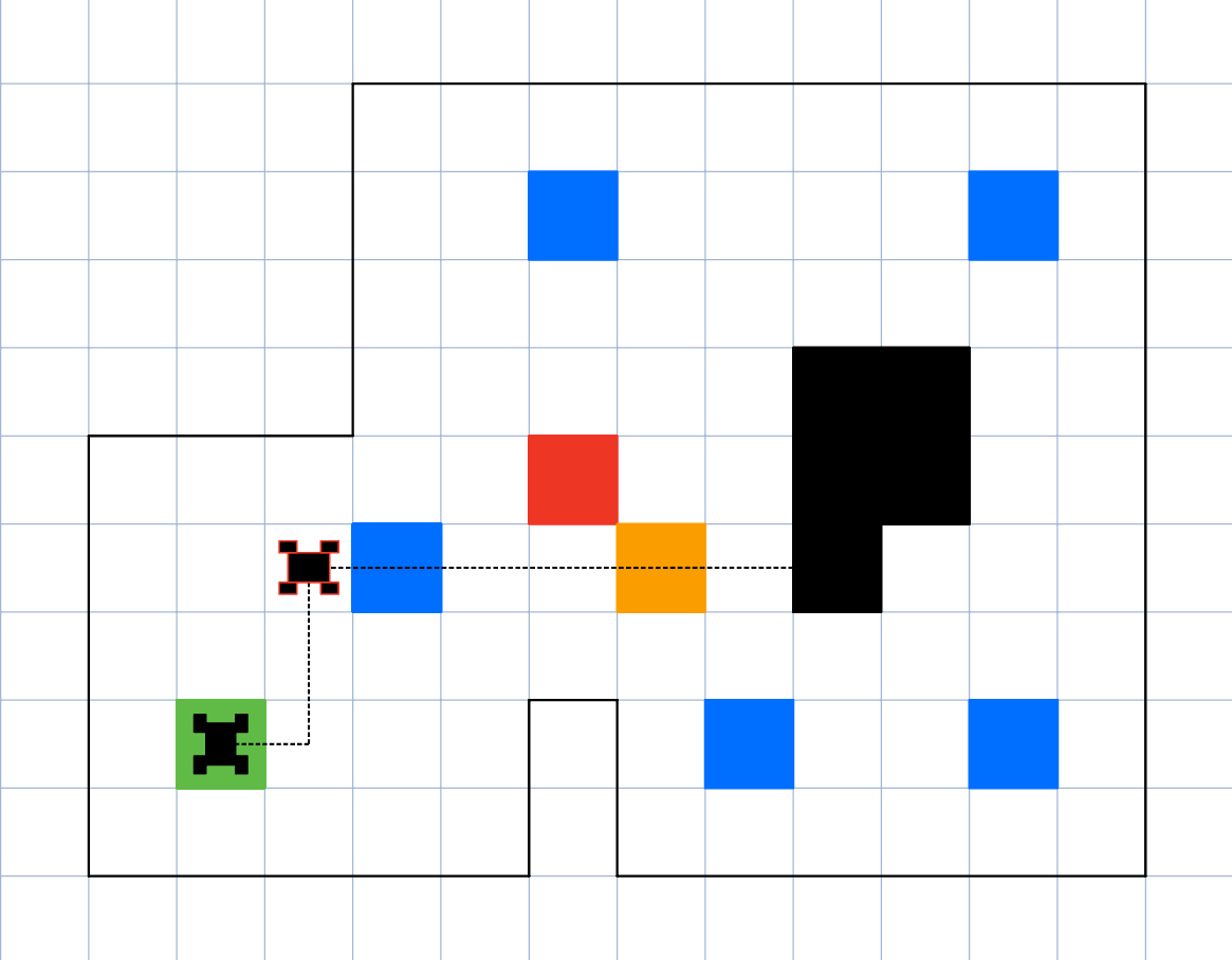
The most optimized path to the first waypoint required diagonal movement directly from the start.
However, due to the limited range of my ToF sensors, I was unable to use linear PID to approach the first waypoint. Although angular PID allowed me to rotate accurately toward the target, the opposite wall was out of sensing range. As a result, the system could not detect when the waypoint, marked in orange, was reached using linear PID.
An alternative was to use open-loop forward motion, estimating the required duration to reach the waypoint. However, inconsistencies caused by battery depletion and general variability in the vehicle’s performance made this approach unreliable. The error introduced from these inconsistencies would propagate throughout the remainder of the path, leading to failed runs. Furthermore, because the vehicle lacked robust localization, I couldn’t correct its position after the open-loop command.
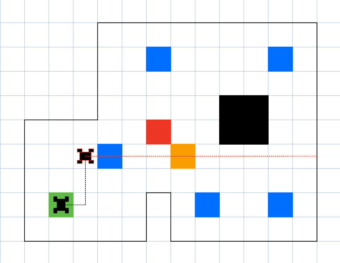
As a result, I planned a new route that avoided diagonal movement altogether.
Even along this new path, I encountered similar issues. The wall opposite to the orange waypoint was still out of ToF range, making linear PID unusable. As seen in previous labs, when the wall was not detected, the sensor would return arbitrary values. In this case, the car received values below the setpoint and falsely believed it had overshot, prompting it to reverse.
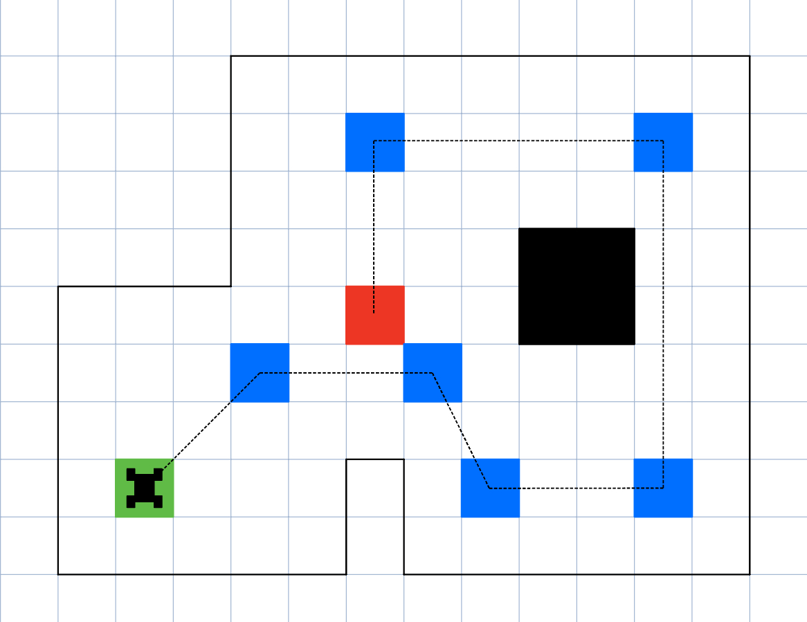
To resolve this, I adjusted the route so that walls remained within sensing range throughout the path. This new path skipped two waypoints but maintained reliable control performance.
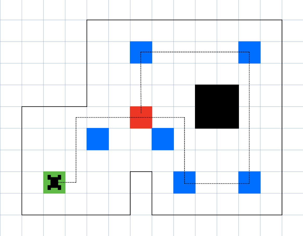
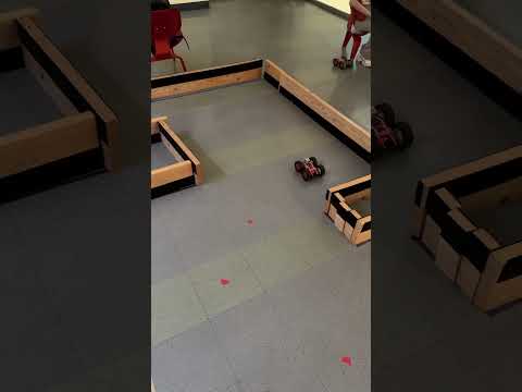
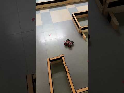
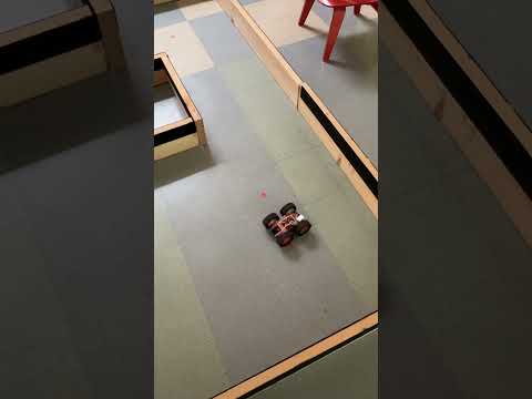
With this modified path, I was able to achieve consistent and successful runs, as shown in this video.
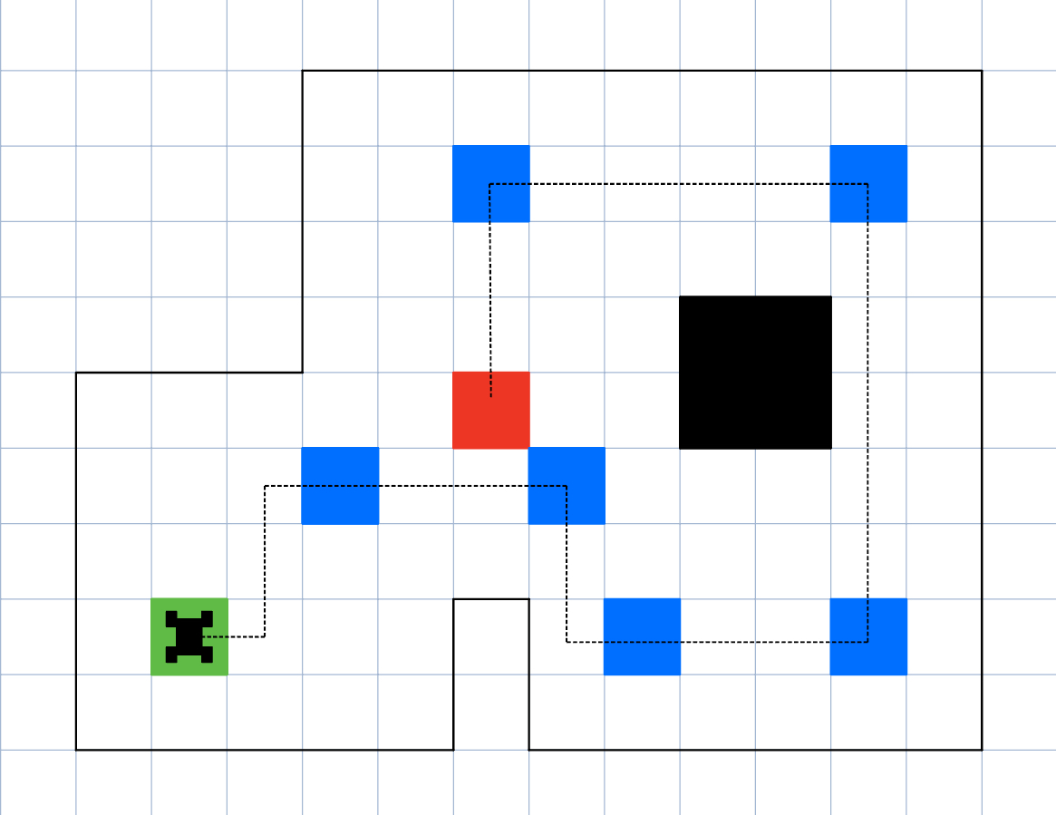
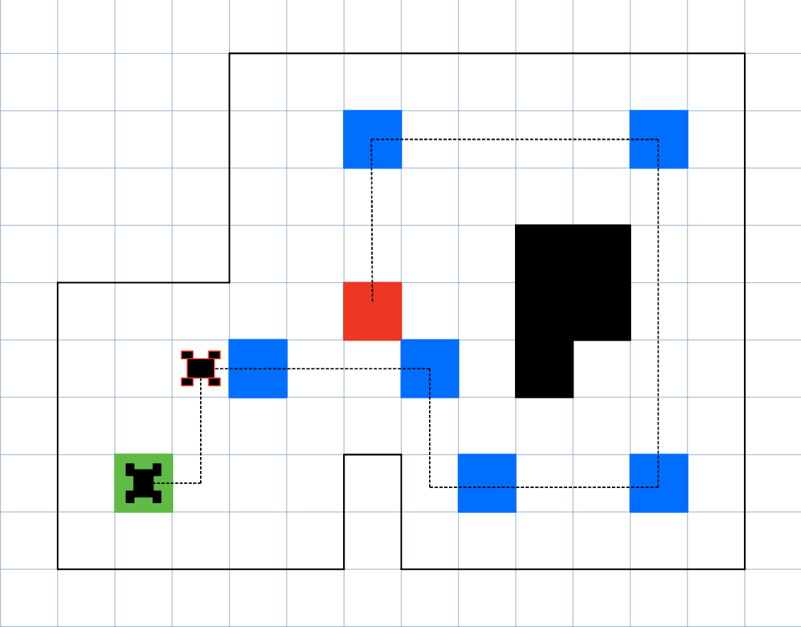
Still, I wanted to demonstrate full waypoint traversal despite ToF limitations. With a small modification to the world layout, I created a feasible path that passed through all waypoints. The effectiveness of this route is demonstrated in the following two videos.
Summary
I deliberately chose not to move along diagonal paths. This decision relates to the limited range of my ToF sensors. If the car were to move diagonally, the opposite wall, used as a reference for linear PID control, would fall outside the sensor's effective range, leading to unpredictable behavior. This limitation also caused issues when trying to reach certain waypoints when not moving on diagonals. In one case, the car attempted to perform distance-based PID on a wall that was not within sensing range. As a result, it incorrectly would move in reverse.
To address this, I experimented with two approaches:
Route Adjustment: In one attempt, I intentionally skipped the second and third waypoints to take a route that ensured a wall was always within sensing distance. This allowed my linear PID controller to function reliably, and the car navigated smoothly through the modified path.
Environmental Modification: In a second approach, I placed a block in a strategic location to bring a wall within range. This allowed the car to use the new surface for PID control and successfully navigate through all the waypoints, including the previously problematic ones.
Refrences
I completed Lab 12 independently. I did not work with or consult other students in developing my approach or implementation. I did not reference previous submissions. I used ChatGPT to assist with Arduino code generation, as well as for text editing and revision.