Lab 2
In the Lab 3 we are tasked with integrating distance sensors with our artemis microcontroller.
Prelab
In our lab kit, we are provided with VL53L1X Time-of-Flight (ToF) sensors. When strategically mounted on our car, we will use these to acquire meaningful distance data. To begin, I referred to the datasheet. When initialized, both accelerometers have the same I2C address, and in this lab, we are responsible for handling the addressing such that they are both readable. I have yet to commit to ToF placement on my vehicle, so I opted to use the two long QWIIC connect cables to give me more freedom when installing them in my car. Approaches I am entertaining place both in the front, or one in the front, and one on the side. Depending on the configuration, it will miss obstacles behind and on the left and/or right. Considering that the car moves through space either forward or backward, and backward movement can be replaced with a 180-degree turn, the particular locations of the blindspots can be accounted for in the code.
Soldering
We begin by attaching a JST connector to one of our 650mAh batteries to power our microcontroller from the batteries. To ensure a successful JST connection and battery function, I sent BLE messages back and forth between my computer and the Artemis to validate the untethered connection. I used the ECHO command for this task.
I2C
After soldering the ToF to the QWIIC connect, we connect to the I2C breakout board and use Example1_wire_I2C to find the sensor.
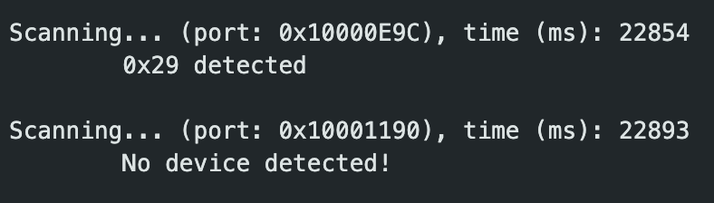
The sensor has an address of 0x29. Although the datasheet states that default I2C address is 0x52, the address returned by the scan is likely the most significant seven bits ignoring the read/write bit.
ToF Testing
After finding the sensor, I began data collection. The sensor has three modes: short, medium, and long. The data sheet and experimental testing show that short is more accurate but has less range. The datasheet also indicates that the short setting is more resistant to ambient lighting conditions and has shorter ranging time. Due to these factors, it felt like a more reasonable choice because the robot would operate in various settings.

To understand the ToF in its short setting, I collected data comparing the measured and actual values. Furthermore, I used two different surfaces at each distance increment, a white glossy surface, and a matte black surface, to collect data on any potential discrepancy introduced by color and texture. I created a Bluetooth command that collects 50 ToF measurements and transmits them to my computer for processing in Jupyter lab.
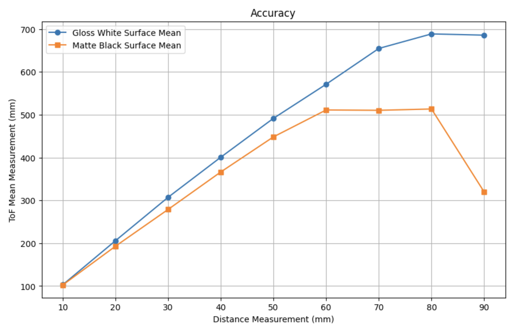
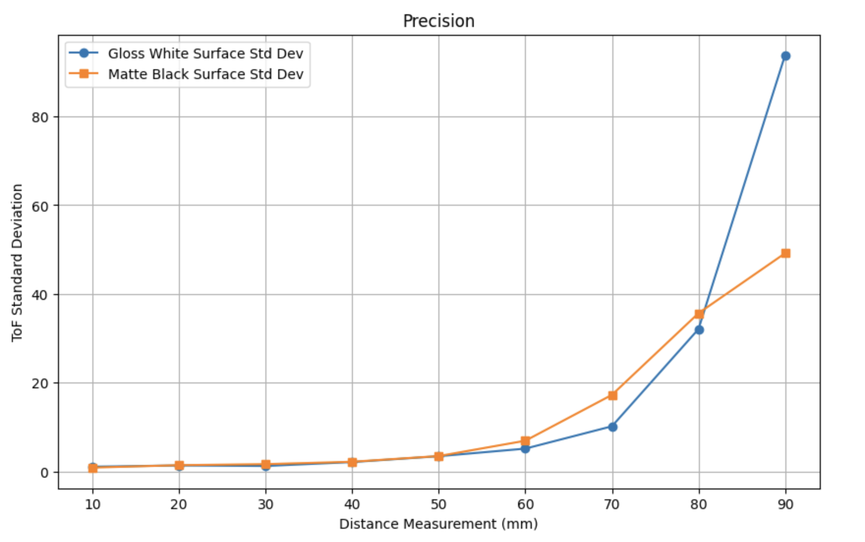
Both setups display linear behavior and maintain decent accuracy up to about 500 mm. However for the matte black backdrop, the linear trend does not follow the measured values beyond the initial measurement despite having a low standard deviation. Beyond 600 mm, even the white glossy surface measurements begin to diverge from the actual values, accompanied by an increase in standard deviation. As the distance increases past 600 mm, the sensor’s accuracy decreases and variability rises significantly. Under the tested environmental conditions, reliable, meaningful data is generally confined to distances under 500 mm. Across all these measurements, there was an average ranging time of 51.56 ms.
Dual ToF
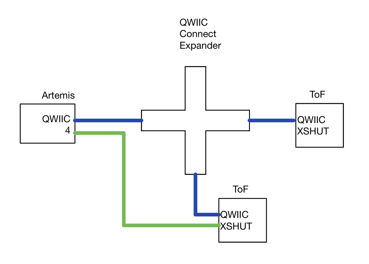
To resolve potential conflicts when connecting both sensors to the I2C breakout, I manage their addressing by controlling the XSHUT pin. The XSHUT of one of the sensors is connected to pin 4 on my microcontroller. Addressing is handled using the following steps.
- Set the XSHUT pin low to keep sensor 2 powered off initially.
- Configure sensor 1 with a new I2C address.
- Enable sensor 2, allowing it to initialize with the default address.
This approach ensures that both sensors can communicate independently without addressing conflicts.
Once the sensors are successfully initialized, the following code prints Artemis clock to Serial as fast as possible and prints new sensor data whenever it is available.
void setup(void)
{
 pinMode(4, OUTPUT);
 digitalWrite(4, LOW); // Keep sensor2 in shutdown


 sensor1.setI2CAddress(0x30); // setAddress returns 0 on success
 while (sensor1.begin() != 0) // begin() returns 0 on a successful init
 {
   Serial.println("Sensor1 failed to begin.");
 }
 Serial.println("Sensor1 online at address 0x30");

 while (sensor2.begin() != 0)
 {
   Serial.println("Sensor2 failed to begin");
 }
 Serial.println("Sensor2 online at default address 0x29");


 sensor1.setDistanceModeShort();
 sensor2.setDistanceModeShort();
}


void loop(void)
{
 sensor1.startRanging();
 sensor2.startRanging();
 if (sensor1.checkForDataReady()) {
   int distance1 = sensor1.getDistance();
   sensor1.clearInterrupt();
   sensor1.stopRanging();
   Serial.println(distance1);
 }
 if(sensor2.checkForDataReady()) {
   int distance2 = sensor2.getDistance();
   sensor2.clearInterrupt();
   sensor2.stopRanging();
   Serial.print(distance2);
 }
 else{
   Serial.println(millis());
 }
}
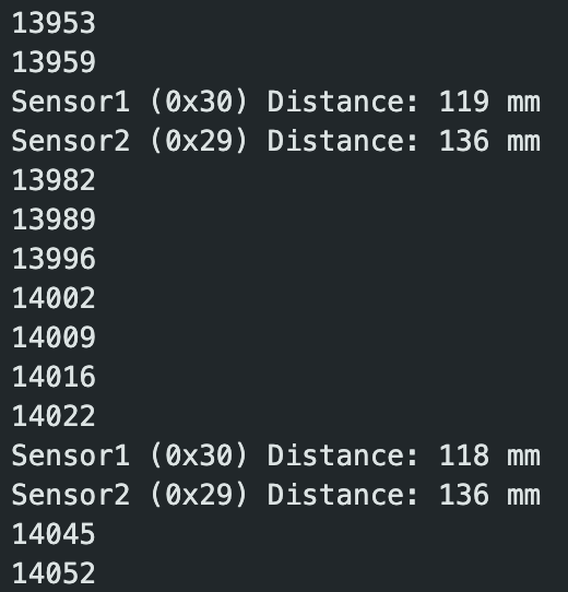
On average, assuming no data is available, it takes the loop about 7ms to execute. The limiting factor is the rate at which the data is available from the ToF. From the observed serial output it’s clear that the loop is executing much faster than the ToF is able to sample new data.
IMU Integration
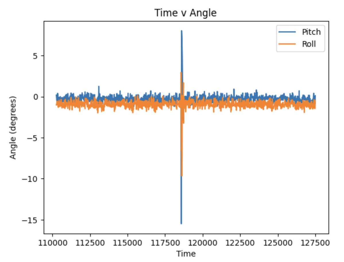
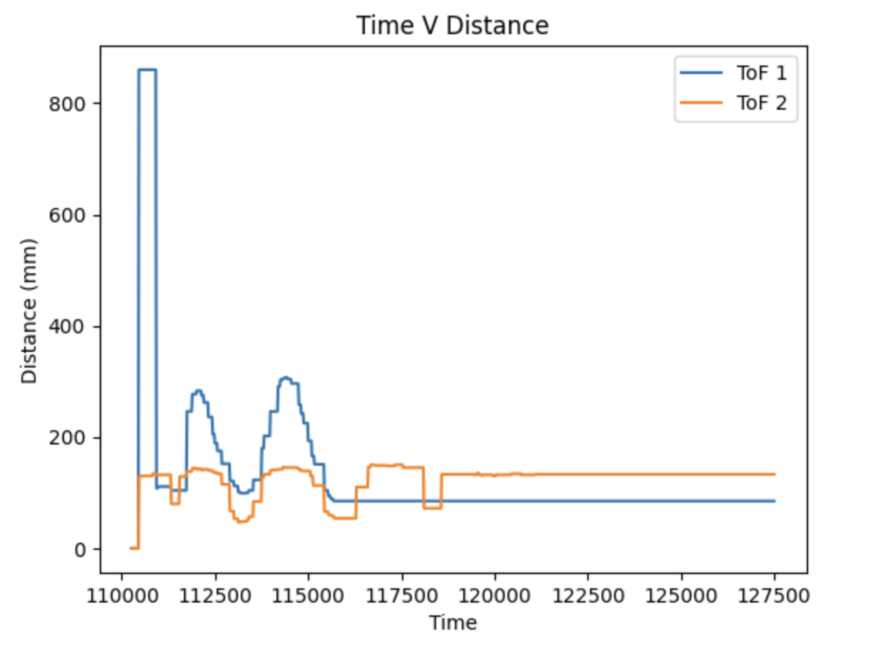
To combine elements of Lab 2 with our work in Lab 3, we were responsible for collecting both time-stamped ToF and IMU data and transmitting it via Bluetooth. Because the IMU uses a different default address, there were no additional address considerations when attaching it to the I2C breakout. By including IMU setup, we can collect IMU data in conjunction with ToF data and transmit it over Bluetooth using the IMU method in Lab 2. This data collection yielded the following plots:
Additional tasks for 5000-level students
Another type of infrared sensor is the structured light 3D scanner. It works by projecting infrared light patterns onto a surface and analyzing the distortions perceived by an infared sensor to determine both distance and geometry. Unlike ToF sensors, structured light scanners offer a wide field of view and can capture details of 3D structures and objects. They tend to be expensive and require significant processing to interpret the data. An alternative infrared distance sensing approach is lidar. Lidar works by sending a laser pulse and then gathers distance based on the duration it takes to receive a reflection. Lidar is typically used for longer range applications however its range is limited by the amount of power producing the laser making it costly.
From my initial testing of the ToF, where I collected data with two separate surfaces as a backstop, one being a white and glossy surface and the other being a matte black surface, there is an observable discrepancy in the measured data, indicating that the ToF sensor is sensitive to different colors and textures. Intuitively, a glossy surface would reflect infrared light better, which facilitates better measurement. Additionally the black surface may be absorbing some infrared light hindering the ability to get accurate measurements.
Refrences
I referenced Nila's webpage, which was recommended in class, to guide the formatting and content of my report. To assist with testing and generating test code and plots, I utilized ChatGPT. I found information regarding structured light scanners here and lidar here. I engaged in some general discussion about the lab with Aidan McNay.