Lab 4
Objective
In lab 4, we were tasked with transitioning our car from manual to open-loop control. We were responsible for integrating our Artemis, motor driver, and sensors into the vehicle and having it perform simple movements.
Prelab
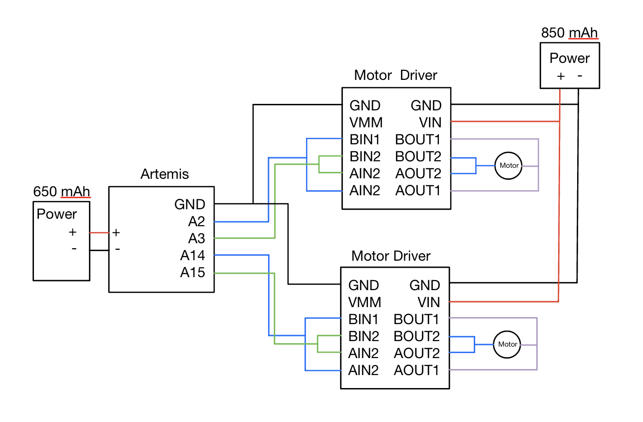
The prelab began with referring to the dual motor driver documentation and datasheet. We parallel-coupled the dual motor driver such that instead of driving two motors, it could supply double the current to a single motor. I used pins A14 and A15 for one motor driver, and for the other, I used A2 and A3. I selected these pins because they were PWM compatible, and they optimized the wire routing for my car configuration. Separate batteries are used to power the Artemis and motor drivers/motors mitigate the EM noise on microcontroller signals and connections and maximize current supply.
PWM
We verified the PWM waveform integrity using the oscilloscope before connecting the motor drivers to the motors and battery. The analog write function takes in duty cycle as a value in range 0 - 255. I drove one signal line with a 50% duty cycle square wave to verify functionality while the other signal line was pulled low. Because the motors are responsible for spinning in both directions, I tried the inverse case, flipping the pin pulled low with the pin receiving the PWM. The VIN and GND pins on the output side were connected to an external power supply set to 3.7V, which was recommended to me in office hours. The motor driver input voltage range is 2.7V to 10.8V provided on the datasheet. The scope probes were placed on OUT1 and OUT2. Once I verified that the PWM was working as expected, I performed the same test on the other motor driver. The following code was used to generate PWM signals:
const int AIN1 = 14;      // Motor direction control pin 1
const int AIN2 = 15;      // Motor direction control pin 2


void setup() {
 pinMode(AIN1, OUTPUT);
 pinMode(AIN2, OUTPUT);

 digitalWrite(AIN2, LOW);

 analogWrite(AIN1, 128);
}


void loop() {
}
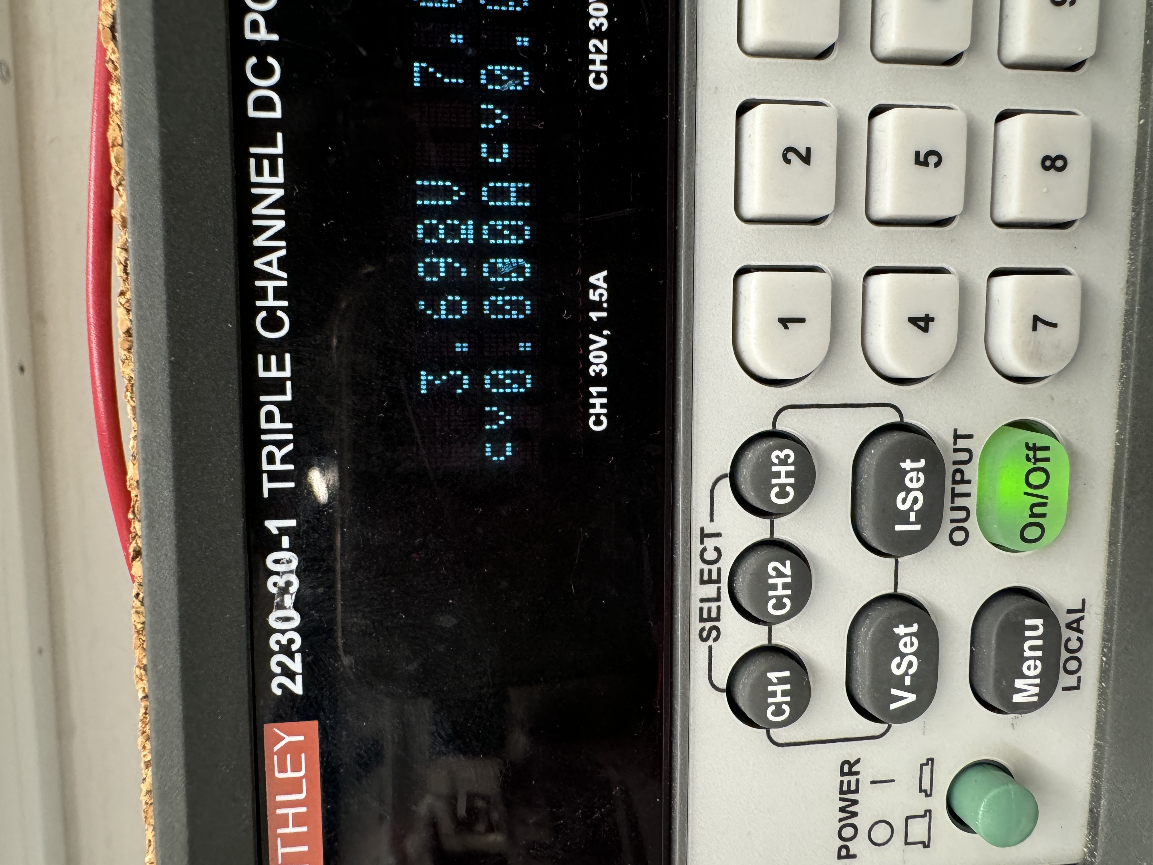
Power Supply:
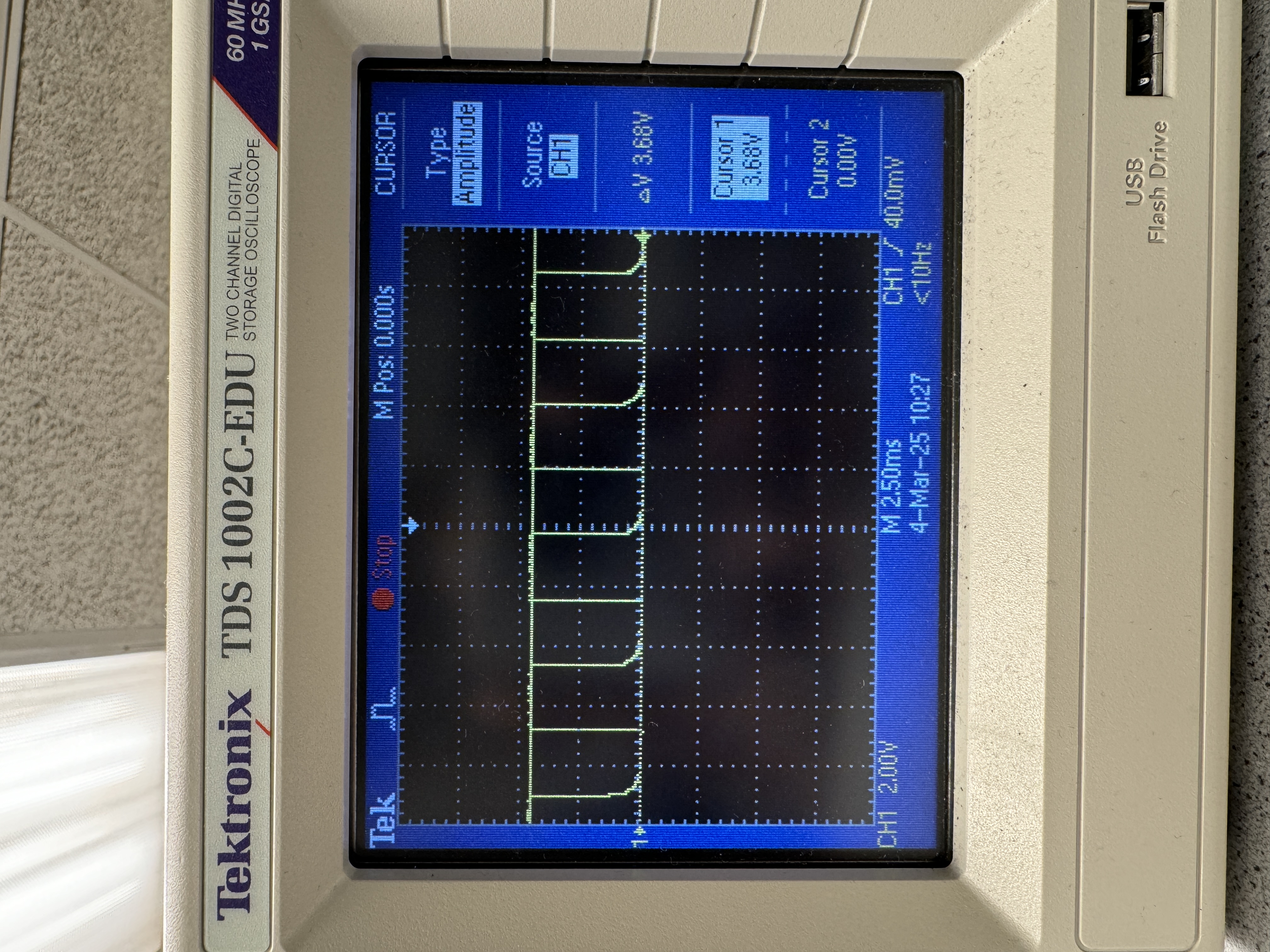
Motor Driver 1 Oscilloscope Output:
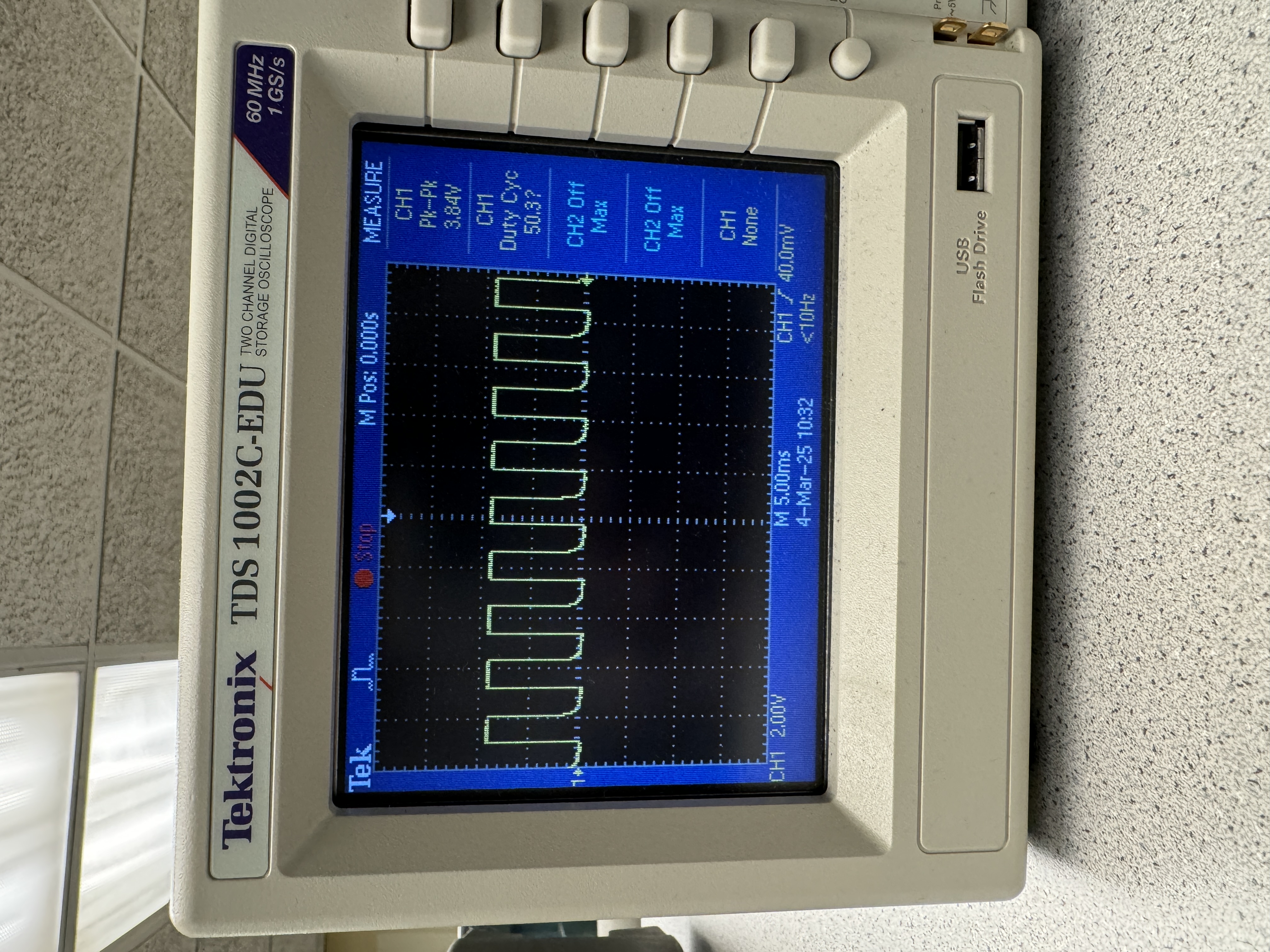
Motor Driver 2 Oscilloscope Output:
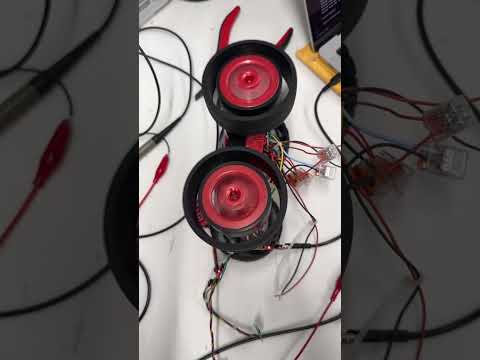
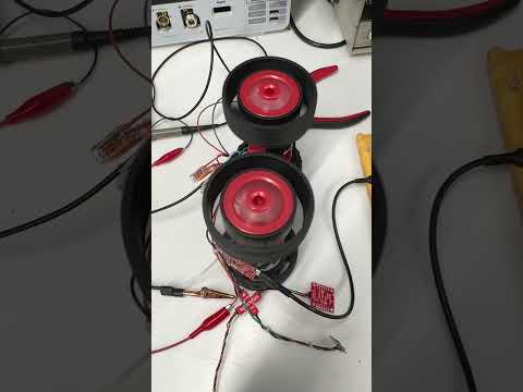
Since we had already verified the motor driver output signal, the next step was to connect the motors to the drivers. Running the same code with the car connected to the power supply yielded the following results:
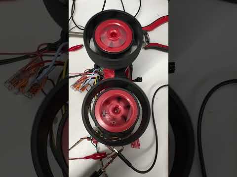
I then ran a modified version of the program which allowed me to once again verify the multi-directional motion, as demonstrated in this video:
Open Loop
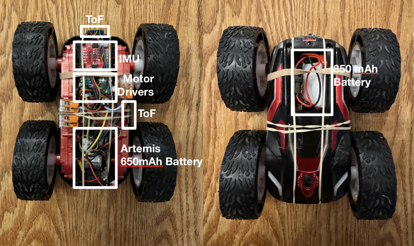
Following the bench test, I finished assembling my car to begin open loop and untethered testing.
For this step I created two new bluetooth commands, SPIN_MOTOR and SPIN_MOTOR_1. The first command allowed for the direction and duty cycle to be set on each motor. I opted for this approach because it allowed me to calibrate the motors and perform lower limit tests without having to flash new code. The second command allows me to set an initial PWM value and after some time switch to another PWM value. It takes in 4 inputs, initial and secondary PWM value for each motor. The second command was created to assist with the 5000 level additional exercise.
case SPIN_MOTOR:
           int direction1, dutyCycle1, direction2, dutyCycle2;

           success = robot_cmd.get_next_value(direction1);
           if (!success) return;

           success = robot_cmd.get_next_value(dutyCycle1);
           if (!success) return;

           success = robot_cmd.get_next_value(direction2);
           if (!success) return;

           success = robot_cmd.get_next_value(dutyCycle2);
           if (!success) return;

           dutyCycle1 = constrain(dutyCycle1, 0, 255);
           dutyCycle2 = constrain(dutyCycle2, 0, 255);


           if (direction1 == 1) {
               digitalWrite(AIN2, LOW);
               analogWrite(AIN1, dutyCycle1);
           } else {
               digitalWrite(AIN1, LOW);
               analogWrite(AIN2, dutyCycle1);
           }


           if (direction2 == 1) {
               digitalWrite(BIN1, LOW);
               analogWrite(BIN2, dutyCycle2);
           } else {
               digitalWrite(BIN2, LOW);
               analogWrite(BIN1, dutyCycle2);
           }

           delay(2000);

           analogWrite(AIN1, 0);
           analogWrite(AIN2, 0);
           analogWrite(BIN1, 0);
           analogWrite(BIN2, 0);

           break;


       case SPIN_MOTOR_1:
           int dutyCycle3, dutyCycle4, dutyCycle5, dutyCycle6;


           // Get first set of duty cycles
           success = robot_cmd.get_next_value(dutyCycle3);
           if (!success) return;


           success = robot_cmd.get_next_value(dutyCycle4);
           if (!success) return;


           // Get second set of duty cycles
           success = robot_cmd.get_next_value(dutyCycle5);
           if (!success) return;


           success = robot_cmd.get_next_value(dutyCycle6);
           if (!success) return;

           dutyCycle3 = constrain(dutyCycle3, 0, 255);
           dutyCycle4 = constrain(dutyCycle4, 0, 255);
           dutyCycle5 = constrain(dutyCycle5, 0, 255);
           dutyCycle6 = constrain(dutyCycle6, 0, 255);

           digitalWrite(AIN1, LOW);
           digitalWrite(BIN2, LOW);

           analogWrite(AIN2, dutyCycle3);
           analogWrite(BIN1, dutyCycle4);

           delay(3000);

           analogWrite(AIN2, dutyCycle5);
           analogWrite(BIN1, dutyCycle6);

           delay(5000);


           // Stop the motors
           analogWrite(AIN1, 0);
           analogWrite(AIN2, 0);
           analogWrite(BIN1, 0);
           analogWrite(BIN2, 0);

           break;
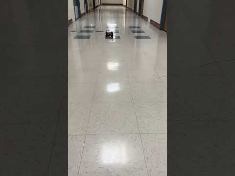
To overcome friction, I began with a PWM of 20 on both motors, I increased by 5 until I was able to get the car to move and then I decreased by 1 until the car stopped moving. At full charge this value was around 42 but as the battery decreased the PWM value increased to 50~55. For continued open loop control I was able to create turning behavior using my SPIN_MOTORS command where I had 1 set of wheels spin forward and another spin backwards. For straight line calibration I set a 2 second time limit on the motors and began with both motors on a 50 percent duty cycle. There was a noticeable drift to the left. With a 1.25 calibration constant on the left motor, at full battery charge I was able to get the vehicle to travel in a straight line.
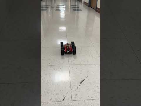
In this video it demonstrates forward motion and then slow turning created by a small duty cycle value.
Additional tasks for 5000-level students
I did not measure the PWM frequency on the oscilloscope and could not find information regarding the Artemis redboard nano PWM frequency. From what I found on the internet, comparable boards have a sampling rate of around 500 Hz to 1 kHz. Considering that the driver has an internal frequency of 50 kHz, these PWM frequencies should be fine, which is supported by our experimental results. If the PWM frequency is configured to run faster, it has the potential to decrease current and voltage ripple, creating a smoother operation.
Experimentally, I found that the lowest PWM value that kept the robot in motion once it had overcome friction was 36. Using the SPIN_MOTOR_1 command, I got the car moving with the previously found minimum duty cycle. I then increased the duration it would run at the second duty cycle to 10 seconds and began decreasing the second interval duty cycle. I got it down to 36, and if I were to go lower than this value, the car would come to a stop before the end of the second time interval.
Refrences
I referenced Nila's webpage, which was recommended in class, to guide the formatting and content of my work. Additionally, I used this webpage to gather information about the PWM frequency of analogWrite(). To assist with testing and generating code, I utilized ChatGPT.