Lab 6
Objective
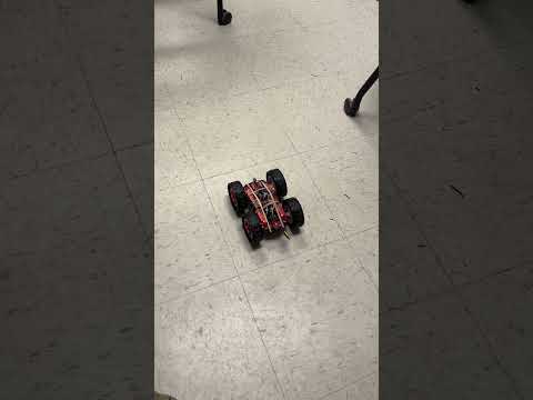
Lab 6 continued PID. In Lab 5, PID control was used to control distance from the wall using data from our Time of Flight (TOF) sensors. In Lab 6, we used the same principles to control orientation based on a yaw angle measurement. As a 5000-level student, I was responsible for completing this task using a PI or PID controller.
Prelab
Using a similar approach to lab 5, I am able to send my PID parameters as well as my minimum and maximum PWM values over Bluetooth. This approach allows me to quickly experiment with different values, making the tuning process faster and more efficient. In Python, I call my PID command and send five values: Kp, Ki, Kd, PWM_MIN, and PWM_MAX.
ble.send_command(CMD.PID, "0.01|0.0000008|0.0007|100|200")
These Bluetooth commands are unpacked and assigned to the globally defined variables in Arduino. Once the variable assignment is complete, it toggles a flag, which prompts PID to run for 5 seconds in a loop.
case PID:
           success = robot_cmd.get_next_value(Kp);
           if (!success) return;


           success = robot_cmd.get_next_value(Ki);
           if (!success) return;


           success = robot_cmd.get_next_value(Kd);
           if (!success) return;


           success = robot_cmd.get_next_value(PWM_MIN);
           if (!success) return;


           success = robot_cmd.get_next_value(PWM_MAX);
           if (!success) return;


           PID_flag = true;
           break;
Digital Motion Processor (DMP)
As we explored in lab 2, although gyroscope data is low in noise, there is a reasonable amount of drift. With this being the case, using gyro data to compute yaw angles would cause issues over time as the measured yaw drifts. One way to address this issue is utilizing the onboard digital motion processor (DMP) to mitigate this drift. The DMP module uses sensor fusion of the accelerometer, gyroscope, and magnetometer to minimize noise and drift. I initialize the DMP using this code:
void setup() {
   Serial.begin(115200);
   Wire.end();
   delay(500);
   Wire.begin();
   bool initialized = false;
   while (!initialized) {
       myICM.begin(WIRE_PORT, AD0_VAL);
       if (myICM.status == ICM_20948_Stat_Ok) {
           initialized = true;
       } else {
           SERIAL_PORT.println("Retrying ICM-20948 initialization...");
           delay(500);
       }
   }

   bool dmpSuccess = true;
   dmpSuccess &= (myICM.initializeDMP() == ICM_20948_Stat_Ok);
   dmpSuccess &= (myICM.enableDMPSensor(INV_ICM20948_SENSOR_ORIENTATION) == ICM_20948_Stat_Ok);
   dmpSuccess &= (myICM.setDMPODRrate(DMP_ODR_Reg_Quat9, 2) == ICM_20948_Stat_Ok);
   dmpSuccess &= (myICM.enableFIFO() == ICM_20948_Stat_Ok);
   dmpSuccess &= (myICM.enableDMP() == ICM_20948_Stat_Ok);
   dmpSuccess &= (myICM.resetDMP() == ICM_20948_Stat_Ok);
   dmpSuccess &= (myICM.resetFIFO() == ICM_20948_Stat_Ok);
   if (!dmpSuccess) {
       Serial.println("DMP initialization failed!");
       while (1) { } // Halt if DMP fails to initialize.
   } else {
       Serial.println("DMP initialized successfully!");
   }

    # Initialize TOF


    # Initialize BLE
}
In my loop I’m then able to get yaw values using this code:
icm_20948_DMP_data_t dmpData;
myICM.readDMPdataFromFIFO(&dmpData);
if ((myICM.status == ICM_20948_Stat_Ok) || (myICM.status == ICM_20948_Stat_FIFOMoreDataAvail)) {
   if ((dmpData.header & DMP_header_bitmap_Quat9) > 0) {
       // Convert quaternion components from fixed point (scaled by 2^30)
       double q1 = ((double)dmpData.Quat9.Data.Q1) / 1073741824.0;
       double q2 = ((double)dmpData.Quat9.Data.Q2) / 1073741824.0;
       double q3 = ((double)dmpData.Quat9.Data.Q3) / 1073741824.0;
       double q0 = sqrt(1.0 - ((q1 * q1) + (q2 * q2) + (q3 * q3)));
       // Compute current yaw (in radians) from quaternion.
       double yaw = atan2(2.0 * (q0 * -q3 + q1 * q2),
                          1.0 - 2.0 * ((q1 * q1) + (q3 * q3)));
       // Convert yaw to degrees
       double current_yaw_deg = yaw * 180.0 / M_PI;
The DMP returns quaternion components which need to be converted to Euler angles which I did using the code in the example. The DMP uses a FIFO, which is read via I2C. When I initialized my DMP, I had the output rate set to its maximum, and I got nan when retrieving the data. It resolved this issue when I slowed the sample rate to ~10Hz. The FIFO has a size of 512 bytes, meaning it may fill up if it is not read fast enough. To prevent this, I ensure that it is being sampled as fast as possible by minimizing the amount of computation and printing between reads. From the datasheet it states that the gyroscope has a programmable FSR of up to +/-2000 dps which should be sufficient for our use cases. I believe that the value passed in to myICM.enableDMPSensor will inform the maximum dps based on the configurations associated with the setting however I don’t believe we can configure it manually while using the DMP.
Derivative Discussion
Generally speaking, it doesn’t make sense to take the derivative of a signal that is the integral of another signal. If we were using raw gyro data, we could effectively get the derivative by taking the raw value returned by the gyro instead of integrating it to get position and then taking the derivative to get speed. However, in our case, we are not using gyro data; we are using DMP data, which is partially informed by the gyro. Since we don’t receive data as angular speed, we must take the derivative to include the D term in our PID. If the setpoint suddenly changes, this can cause a sudden jump in the derivative term, which is a derivative kick. To help mitigate this, the derivative term can be filtered to minimize the influence of these sudden changes. In my implementation, I chose not to filter the derivative term because it didn’t seem necessary.
P Control
The first step in this lab was calibrating motor rotation. It took a larger PWM value to get the motors to spin backward than forwards, so I needed to adjust the scaling factors for both rotation directions. Once I could rotate with minimal travel, I began implementing P control. I wanted to analyze how my car performed when changing setpoints. I adjusted my overall PID to run for 6 seconds. The initial setpoint was 0 degrees; after 2 seconds, it would switch to 90 degrees. My initial approach was based on several assumptions, which yielded bad results. The first assumption was that the DMP would immediately start providing good data. In my starting implementation, I observed erratic behavior. When analyzing my error plot, I noticed that the initial DMP values did not accurately reflect the actual position. To address this, before beginning PID, I read DMP values for 2 seconds and discard the data, giving the data a chance to stabilize before using it to inform my PID control. The second assumption was that if my car had been stationary following stabilization, the DMP data would have zeroed around that position. Once I added data stabilization, I still observed a noticeable initial correction upon PID start. When I analyzed the DMP data, I noticed that the stabilized data would settle at +/-10 degrees. To zero around the initial position, I took the first yaw value returned by the DMP and used it as an offset to zero my angular measurement.
void loop() {
   BLEDevice central = BLE.central();
   if (central) {
       Serial.print("Connected to: ");
       Serial.println(central.address());
       while (central.connected()) {
           write_data();
           read_data();


           if (PID_flag) {
               # Wait 2 seconds before starting PID control
               unsigned long stabilizationStart = millis();
               while (millis() - stabilizationStart < 2000) {
                   icm_20948_DMP_data_t dummyData;
                   myICM.readDMPdataFromFIFO(&dummyData);
               }

               bool yaw_offset_set = false;
               double yaw_offset_deg = 0.0;
               start_time_1 = millis();
               while (millis() - start_time_1 < 10000 && PID_flag && central.connected()) {
                   icm_20948_DMP_data_t dmpData;
                   myICM.readDMPdataFromFIFO(&dmpData);
                   if ((myICM.status == ICM_20948_Stat_Ok) || (myICM.status == ICM_20948_Stat_FIFOMoreDataAvail)) {
                       if ((dmpData.header & DMP_header_bitmap_Quat9) > 0) {
                           double q1 = ((double)dmpData.Quat9.Data.Q1) / 1073741824.0;
                           double q2 = ((double)dmpData.Quat9.Data.Q2) / 1073741824.0;
                           double q3 = ((double)dmpData.Quat9.Data.Q3) / 1073741824.0;
                           double q0 = sqrt(1.0 - ((q1 * q1) + (q2 * q2) + (q3 * q3)));
                           double yaw = atan2(2.0 * (q0 * -q3 + q1 * q2),
                                              1.0 - 2.0 * ((q1 * q1) + (q3 * q3)));
                           double current_yaw_deg = yaw * 180.0 / M_PI;

                           # get inital yaw measurement and use it as offset
                           if (!yaw_offset_set) {
                               yaw_offset_deg = current_yaw_deg;
                               yaw_offset_set = true;
                           }

                           double yaw_deg = current_yaw_deg - yaw_offset_deg;

                           # Change set point after 2 seconds
                           unsigned long pid_elapsed = millis() - start_time_1;
                           double setpoint = (pid_elapsed < 2000) ? 0.0 : 90.0;
                           double error = yaw_deg - setpoint;


                           unsigned long now = millis();
                           double dt = (now - last_time) / 1000.0;
                           if (dt <= 0) dt = 0.001;
                           if (dt > 1) dt = 0.00001;
                           last_time = now;


                           integral += error * dt;
                           if (dt == 0.00001){
                             derivative = 0;
                           }
                           else{
                             derivative = (error - last_error) / dt;
                           }
                           last_error = error;

                           double pid_output = Kp * error + Ki * integral + Kd * derivative;
                           double pid_pwm = PWM_MIN + pid_output;


                           pid_pwm = constrain(pid_pwm, PWM_MIN, PWM_MAX);
                           int pwmValue = (int)pid_pwm;


                           yaws[index_1] = yaw_deg;
                           errors[index_1] = error;
                           time_stamps[index_1] = now;


                           if (pid_output >= 0) {
                               ### Spin car left ###
                           } else {
                               ### Spin car right ###
                           }
                           index_1++;
                       }
                   }
               }


               analogWrite(AIN1, 0);
               analogWrite(AIN2, 0);
               analogWrite(BIN1, 0);
               analogWrite(BIN2, 0);

               ### Transmit Data ###


               PID_flag = false;
               index_1 = 0;
           }
       }
   }
}
For my P control I began by setting my P value to 0.01. This value worked quite well resulting in relatively small oscillations around the set point.
Rather than beginning to tune my P value, I chose to increase my DMP sampling rate from 10Hz to 20Hz which resulted in a slight decrease in oscillation. Yielding the following results:
PID Control
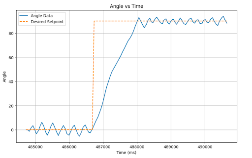
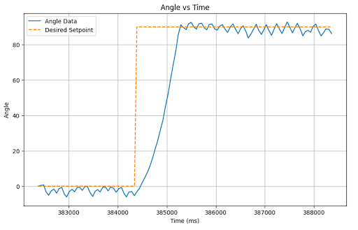
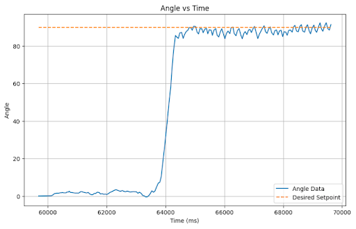
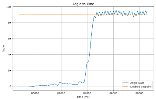
Once I was able to achieve reasonably good P performance, I next switched to PID. I continued to use my P value of 0.01 and decided to just start with the I and D terms from the last lab. I used an initial I of 0.0000001 and a D of 0.0007. Surprisingly these values worked pretty well yielding the following results.

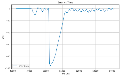
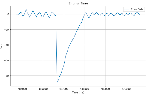
Observing these plots, there are relatively small oscillations around the setpoint however we do observe a small steady state error. I tried to address this by increasing the I term from 0.0000001 to 0.0000008.
Tasks for 5000-level students
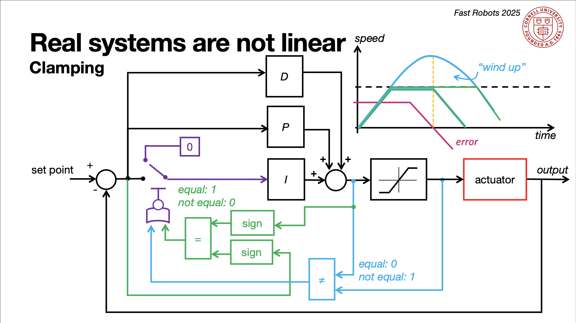
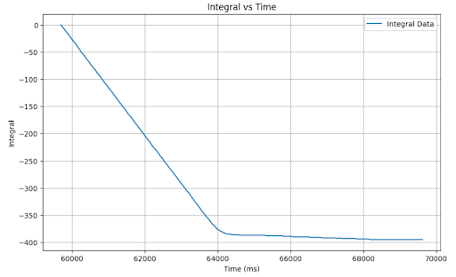
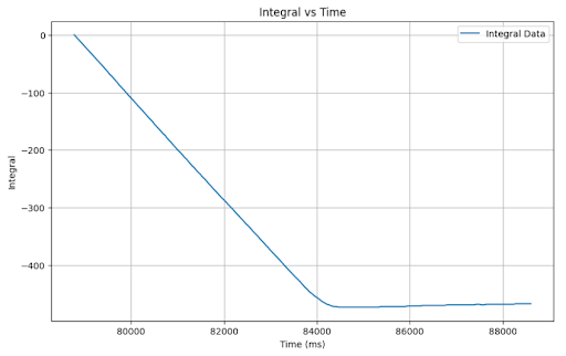
As discussed in lab 5, a danger of PID control is integrator windup. If an error persists for an extended duration, the integral term will continue to grow unbounded, leading to overshoot and large oscillations around your setpoint. Integrator windup can be prevented by clamping your integrator value under the conditions covered in lecture 8.
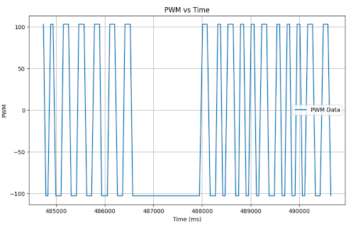
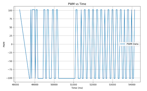
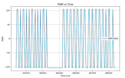
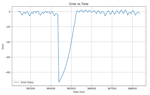
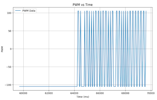
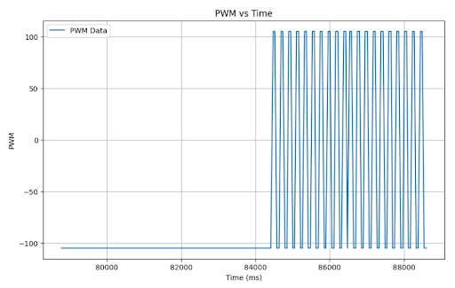
I found that my system was not susceptible to wind up, likely because my integrator term is so small that It would take a very long time to climb to values requiring it to clamp. As observable on my PWM vs time plots, the PWM value stays right around the minimum because the PID output is so small considering the parameters. With this being the case, I may be losing out on some of the potential value of PID; however, I performed pretty well with this implementation. Some chose an approach where if you got close to the setpoint, the PWM output would not be large enough to spin the motors, causing the car to settle. This effectively creates a range of values at which the car comes to a stop. If tuned right, that range can be minimal such that it appears to always settle at the setpoint; however, as the battery drains, that range grows, and I was trying to create a robust system for varying operating conditions.
Here is my controller with no wind-up protection:
Just as an added measure, I included Integrator wind-up protection with the following code:
if(error > 0 && pid_output > 0 && pid_output + PWM_MIN == PWM_MAX || error < 0 && pid_output < 0 && pid_output - PWM_MIN == -PWM_MAX){
  integral = integral;
} else {
  integral += error * dt;
}
Considering that in the previous case, it yielded no meaningful change because it never met the wind-up clamping conditions, there is no discernable difference between the no wind-up protection and the wind-up protection which can be seen here:
I am cognizant that because my k terms are so small and the int casting that occurs, pid_output never gets large enough to influence the PWM value in most cases. However, the presence of the I and the D terms does influence when that value switches from positive to negative, which yielded observably better results on my car when tested. Although this may not constitute a true PID controller, it yielded the best results in my testing. Additionally, because the I term is so small, the car would need to run in a prolonged state of persistent error to see the negative implications of integrator wind-up.
Refrences
In lab 6 I consulted other students in the course about various elements of the assignment. These students included Annabel Lian, Becky Lee, and Aidan McNay. I also referenced Annabel Lian’s and Stephan Wagner's websites. I used ChatGPT to help with debugging as well as some code generation for plotting data and elements of PID implementation.